


 30 / 228

THERMOSTATS
LINE VOLTAGE
THERMOSTATS
1A11-2
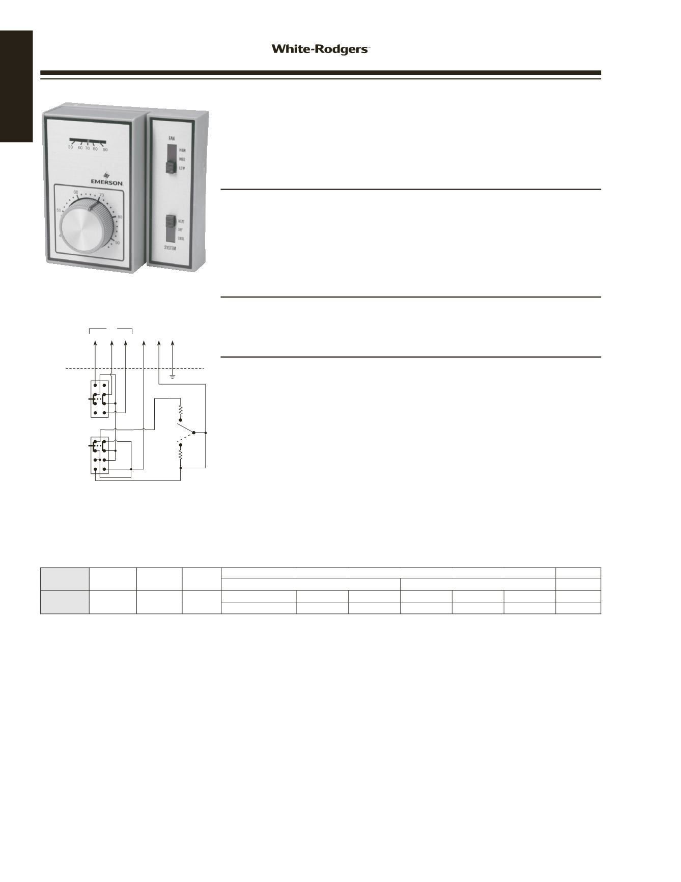
1A11-2 LIGHT DUTY FAN COIL THERMOSTAT
For Direct Control of Line Voltage Valves and/or Blower Motors on
Fan Coil Units Featuring Manual Changeover from Heat to Cool and a
3-Speed Fan Switch, Subbase Included
FEATURES
• Mounts to a standard vertical outlet box or on a two-gang outlet box. May also be
mounted on a 4
”
x 4
”
junction box with an adapter (not provided).
• Wiring color coded for ease of installation.
• 3-speed manual fan switch: High – Medium – Low.
• System Switch: Heat – OFF – Cool. “OFF” breaks both valve and fan circuits.
• Beige color.
SPECIFICATIONS
Dimensions . . . . . . . . . . . 4
1
/
2
”
H x 4
1
/
2
”
W x 2
1
/
4
”
D
Agency . . . . . . . . . . . . U.L. listed and C.S.A. approved
PARTS AND ACCESSORIES
See end of thermostats section for additional parts and accessories
• Thermostat Guards — see pages 34–35
Model
Number
Range Differential
Switch
Action
Contact Ratings
Pilot Duty
Motor Ratings (inductive) Full Load
Motor Ratings (inductive) Locked Rotor 120/240
1A11-2
36 to 90°F
(2 to 32°C)
1.5˚F SPDT
120 VAC
240 VAC 277 VAC 120 VAC 240 VAC 277 VAC 277 VAC
5.5A
2.75A
2.3A
33.0A
16.5A
13.8A
120A
TAN
BLUE
COOL
COOL
HEAT
HEAT
VALVE
(SOL)
L1*
(HOT) GND
HIGH
HIGH
FAN
SWITCH
SYSTEM
SWITCH
MED
FAN
MED
OFF
LOW
LOW
RED
BLUE
RED
ORANGE
BLACK
GREEN
1A11-2
5-wire with ground, for single valve,
manual heat/cool changeover
CUSTOMER
CONNECTIONS
Note: Above FAN and SYSTEM switches shown in
MED and HEAT positions respectively
THERMOSTAT
SCHEMATIC
*L1 is Power In
– Thermostat cycles both fan and valve
– Thermostat cycles fan only (if valve is not used tape orange lead)
– System "OFF" breaks both valve and fan circuits
– Thermostat cycles valve only with continuous fan (interchange valve and L1 leads)
www.white-rodgers.com30