


 6 / 42

C
4
September 2017
Catalog
Number
Fitting
Clamp Range
Ultimate
Strength
lb
U-Bolts
No
Dimensions Inches
Approx
Weight
Each lb
ACSR Aluminum Inches
Size L
H K PD X
SDT286N
SDT286S
SDT286C
None
Socket
Clevis
SA07
CA06
1/0-6/1
to
2/0-6/1
2/0-7 str
to
2/0-19 str
.398
to
.447
25,000
25,000
25,000
4
1/2 111/4 95/8
11/4 5/8
11/16
5.4
6.0
6.4
SDT2112N
SDT2112S
SDT2112C
None
Socket
Clevis
SA1013
CA1013
3/0-6/1
to
4/0-6/1
4/0-7 str
to
4/0-19 str
.502
to
.562
30,000
30,000
25,000
5
1/2 131/8
111/2 13/8
3/4 13/8
8.4
9.9
10.0
SDT2185N
SDT2185S
SDT2185C
None
Socket
Clevis
SA1417
CA1517033
226.8-26/7
to
556.5-18/1
336.4-19 str
to
556.5-37 str
.642
to
.879
50,000
30,000
30,000
5
5/8
17
18 1 1/2 1
17/8
21.0
22.7
22.3
NOTE:
Sag eye ultimate strength is 60% of clamp strength without fitting. Rated slip strength as a percentage of conductor
RBS varies with conductor type, size and stranding. Minimum slip strength rating on standard strength conductors is 40% RBS
(partial tension). For most standard strength conductors, minimum slip strength of this clamp series is 60% RBS (normal tension).
Consult factory for slip strength test data on specific clamp and conductor combinations. Recommended torque on U-bolts:
1/2” — 480 in-lb,
5/8
” — 720 in-lb. Bolt and nut may be substituted for clevis pin by adding suffix “BNK” to catalog number. For
corona-free applications on EHV lines, add suffix “CRF” to catalog number. Example SD130NCRF.
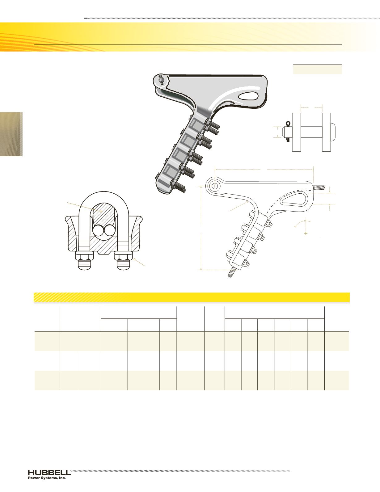
Made with double groove keeper to
accommodate twin conductor. For
transmission line construction with
all aluminum, ACSR or aluminum
alloy conductor. See Catalog Reference
section for maximum conductor temperature
guidelines.
Material:
Body and Keeper
–
aluminum alloy
Hardware
–
galvanized steel
Sockets and clevises
–
galvanized ductile
iron
Deadends—
Bolted
Double Groove Strain Clamp Aluminum
ALUMINUM
SDT2
L
K Dia
Groove
Angle
60º
Single
Groove
Body
H
Double
Groove
Keeper
Tighten to
Recommended
Torque
Section A-A
PD
X
Product Data and Conductor Size