


 15 / 24


CDOIF
Chemical and Downstream Oil
Industry Forum
CDOIF is a collaborative venture formed to agree strategic areas for
joint industry / trade union / regulator action aimed at delivering
health, safety and environmental improvements with cross-sector
benefits.
Guideline – Automatic Overfill Prevention Systems for Terminal Loading Racks v1 Page 15 of 23
5.2
Overfill Prevention System Control Philosophy
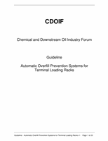
Reference should be made to the simplified cause and effect diagram provided in figure
3 as an example control philosophy for overfill prevention.
Note: automated shutdown valve may
be per bay or per grade
Close FCV - Bay A
Close FCV - Bay B
Close FCV - Bay C
Close S/D Valve - Bay A
Close S/D Valve - Bay B
Close S/D Valve - Bay C
Meter Overrun - Bay A
X
Meter Overrun - Bay B
X
Meter Overrun - Bay C
X
Earth/Overfill Monitor - Bay A
Loss of Earth Signal
X
High Level Detected
X
X
Earth/Overfill Monitor - Bay B
Loss of Earth Signal
X
High Level Detected
X
X
Earth/Overfill Monitor - Bay C
Loss of Earth Signal
X
High Level Detected
X
X
Vapour K-O Pot High Level - Bay A
X
X
Vapour K-O Pot High Level - Bay B
X
X
Vapour K-O Pot High Level - Bay C
X
X
Site ESD Initiated
X
X
X
X
X
X
Figure 3 - Simplified cause and effect diagram
Note that pumps have been excluded from the cause and effect diagram in figure 3.
Determining what action to take for pumps should form part of the risk assessment and
design process.
1.
Electronic Preset/Batch controller
– a healthy earth/overspill interlock from the
earth/overfill monitor provides a healthy permissive signal allowing pump demand