


 84 / 648


Safety and environmental standards for fuel storage sites
Final report
83
8 There are several ways of describing a hazardous scenario. The simplest convention is to
include in the description:
the unwanted serious event (the consequence); and
■
■
its potential cause or causes (initiating event(s)).
■
■
9 Hazardous scenarios can be derived by a number of techniques, eg Hazard and Operability
Studies (HAZOP), Failure Modes and Effects Analysis (FMEA) and What If. These studies will
typically provide at least one initiating event, a high level description of the consequences (although
details of the severity are rarely provided) and may also provide information on the safeguards.
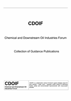
Figure 21
Relationship of LOPA technique to other risk assessment methodologies
10 Once the hazardous scenario has been identified, the LOPA proceeds by defining and
quantifying the initiating events (including any enabling events and conditions) more fully and then
identifying and quantifying the effectiveness of the protection layers and conditional modifiers which
may prevent the scenario from developing or allow it to develop to the defined consequence.
11 It is helpful to adopt a systematic approach to identifying the critical factors which will prevent
the initiating event from leading to a loss of containment and those which, once containment is
lost, will prevent the undesired consequence from occurring. Essentially, this means considering
the analysis in terms of a bow-tie diagram, with the LOPA being the aggregation of a number of
individual paths through the bow-tie diagram which result in the same undesired consequence.
12 It is also important to adopt a systematic approach to identifying the consequence of interest
for the LOPA from the range of possible outcomes. Annex 2 shows the right-hand side of a bow-
tie diagram representing a possible range of consequences to the environment from the overflow
of a storage tank.
13 The critical factors can then be divided between prevention protection layers (on the left-hand
side of the bow-tie), mitigation protection layers (on the right-hand side of the bow-tie) and conditional
modifiers. Further guidance on protection layers and conditional modifiers is given later in this report.
Increasing complexity
Increasing conservatism
Quantified Risk
Assessment
Fault Tree
Analysis
Complex
LOPA
Human Reliability
Assessment
Simple order
of magnitude
LOPA
Risk
graph