


P
E
P
RODUCT MPHASIS ROGRAM
1
The Heavy Duty Air Brake System
The most common brake system in the heavy truck market today is the air supplied s-cam drum brake. The system begins with
an air compressor driven by the engine to supply air to a holding tank (air tank). Most air systems contain an air dryer between
the compressor and air tank to take moisture and other contaminants out of the air.
Air tanks should have a drain valve in the bottom of the tank to purge moisture from
condensation. Moisture and other contaminants in an air system can cause o-rings in
the various air valves to swell and make the plungers stick. This makes the valve in-
operable and it will have to be replaced. Air entering the main air tank passes through
a ball and spring loaded "check valve". This keeps air from bleeding out of the tank
when the compressor is not running.
The main air tank on the tractor is controlled by the foot valve in the cab. When the operator
steps on the pedal of the foot valve, they push down a plunger that allows air pressure to be
released from the main air tank to the relay valves for the steer and drive axle brakes
(pushing down the plunger also covers the quick release diaphragm on the bottom of the
foot valve and closes it off). The air pressure from the foot valve enters the relay valve
through the control line and fills a cavity in the valve with air. This cavity has a diaphragm
with a plunger on the other side of it which controls the flow of air through the relay valve.
When the cavity fills with air, the plunger is pushed down to allow the air in the tank
at the relay valve to be released to the air chambers. Also, when the plunger is pushed
down it covers the quick release diaphragm on the bottom of the relay valve and closes
it off (more about the quick release diaphragm in a minute).
The air from the relay valve tank passes through the brake hose to the air chamber. The
air chamber has a cavity with a diaphragm and a push rod on the other side. The push
rod is attached to the slack adjuster. When this cavity fills with air the push rod moves
the slack adjuster and the slack adjuster rotates the camshaft. The head of the camshaft
between the brake shoes is shaped like an "S" and as it rotates it spreads the brake
shoes apart.
The brake shoes are lined with friction material and contact the brake drum which is
attached to the hub/wheel assembly. The friction material slows down the wheel
assembly by taking the kinetic energy of rotation and turning it into heat. The
hub/wheel assembly mounts the tires which transfers the slowing down of rotation
to the ground and stops the vehicle.
When the operator takes their foot off the pedal, the plunger in the foot valve comes
up; this releases the air in the control line of the relay valve and allows the plunger
in the relay valve to come up and release the air in the air chamber out through the
quick release in the bottom of the relay valve. When the air is released from the air
chamber the push rod return spring moves the push rod back which pulls the slack
adjuster. Pulling the slack adjuster returns the camshaft to its' original position and allows
the brake shoe return spring to release the brake shoes from the brake drum. When the brake
shoes release from the brake drum it stops the slowing down of the vehicle.
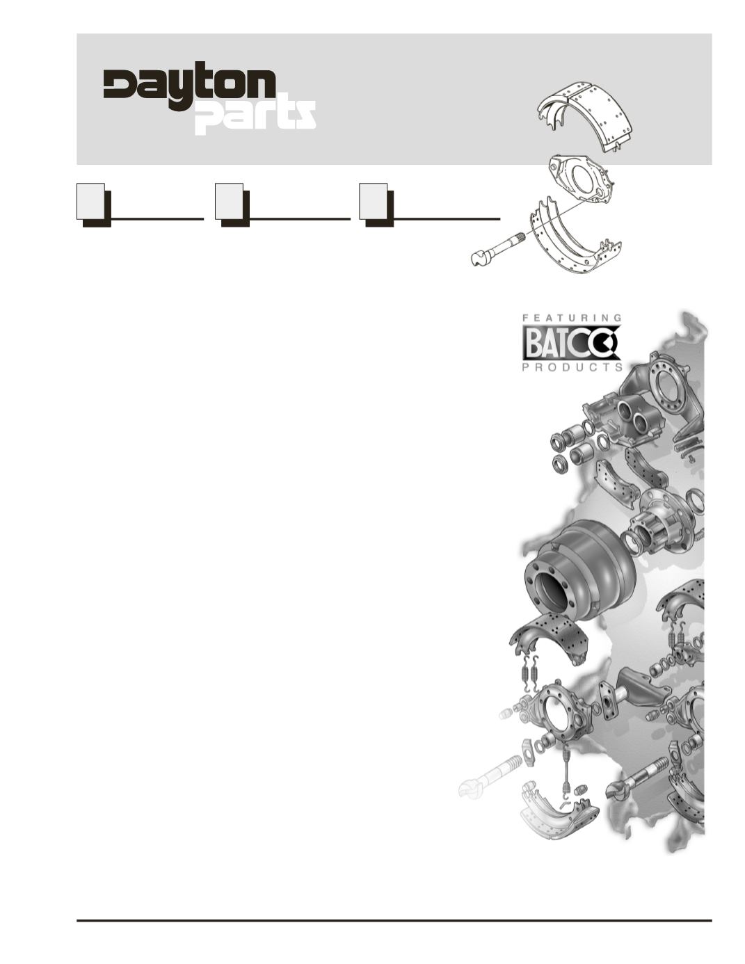
Now that we've completed a brief overview of the air brake system, lets look at the main components in the air system.
TM
PEP Program Number 13
March, 2002
www.daytonparts.comAir
Brake