


 30 / 36

30
combinations. Thought should be given to
the heat generated by the working die which
can be significant in many applications. Heat
absorbed by the tool can be transferred to the
springs resulting in a loss of load and prema-
ture spring failure.
Deflection
Deflection beyond the manufacturer’s recom-
mendation can cause early spring failure.
Check the press or die travel to be sure of the
actual deflection to which the spring will be
subjected. If it is beyond a safe limit, changes
should be made without delay.
Spring Alteration
Each Raymond die spring is carefully engi-
neered to perform within specific areas of
work. Altering the spring such as reducing its
length or number of coils, grinding the inside
or outside diameter, or placing restrictions
on the movement of the coils can cause
early spring failure. Trying to alter a spring by
grinding down its ends can change the temper
of the material and negatively affect spring
performance.
Altering springs from their manufactured state
almost invariably leads to problems and failure.
Don’t gamble an expensive die for the small
amount saved on a cheap alteration.
Corrosion
Frequently, spring failure can be traced to
corrosive elements. Reduction of material
or pitting of the spring will reduce its useful
life. Be alert to conditions that may effect
the spring’s surface such as rust, lubricants,
soaps, chemicals, etc. Clean, protected springs
give the best job performance.
Problems and AnswersProblems & Answers
Most problems that arise in the use of die
springs usually result from improper applica-
tion... failure to take advantage of and protect
the features engineered into the spring.
Spring Failure
Raymond die springs are produced under such
careful controls that manufacturing problems
have virtually been eliminated. Die spring fail-
ure is usually due to either poor spring design
and manufacture or incorrect application of the
spring. The most common problem source is
the use of die springs too close to, or beyond,
the springs’ physical limitations. The solution,
of course, lies with careful selection of die
springs for each application.
Other solutions to common spring problems
are as follows:
Spring Guidance
Raymond die springs are manufactured with
ends ground and squared so that they stand
on their own base and compress evenly under
load. There is a positive relationship between
the spring’s outside diameter and total length
which determines whether or not a spring will
buckle under load.
Generally, if the free length is more than four
times the mean diameter of the spring, it could
have a buckling problem under compression.
This is solved by providing guidance by a
pocket, a rod, or both to reduce buckling. It is
always recommended to provide guidance for
any die spring.
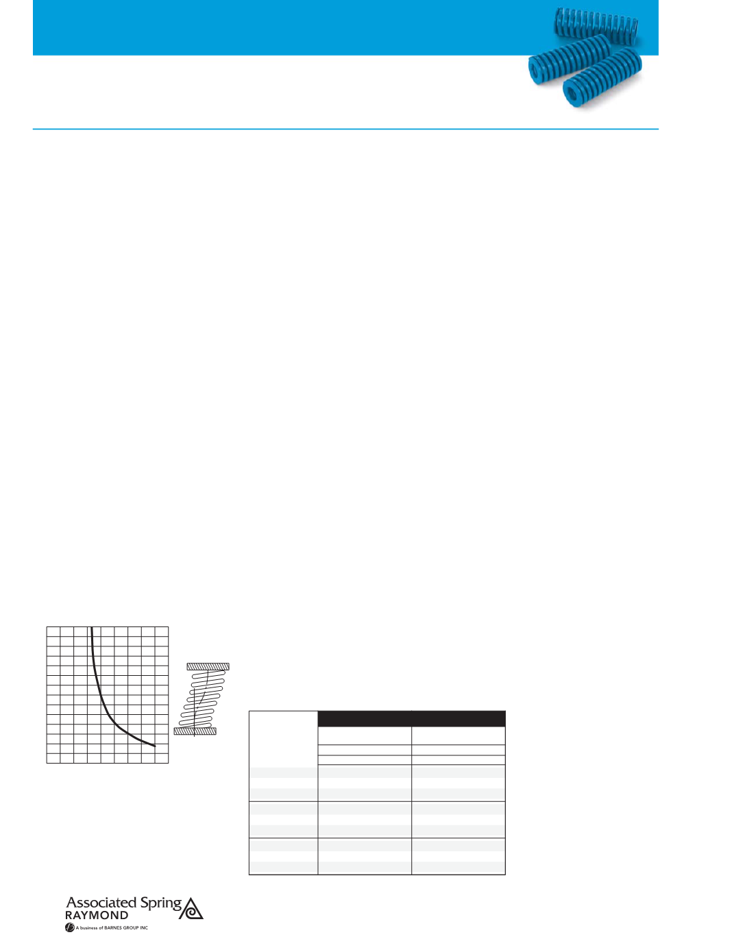
Fig. A (below left)
provides information as to
whether a specific spring with squared, ground
ends is subject to buckling. The curve indicates
that buckling may occur to a squared-and-
ground spring, both ends of which are com-
pressed against parallel plates, if the values
fall above and to the right of the curve.
Holes and Rods
Holes or pockets provided in the die for springs
must be the specified size listed on pages
6 to 28. Springs increase in diameter as they
are compressed. If the hole is undersized, a
wearing or binding action will produce early
spring failure.
Holes also must have flat bottoms with square
corners. This will allow the spring to work on a
flat surface and provide uniform stress on the
coils when the spring is compressed.
Working a spring over a rod also provides
good protection against buckling. Care should
be taken to be sure the rod is smooth. If the
rod is shorter than the spring, it should have a
tapered nose so that there is no danger of the
spring coils coming in contact with a
sharp edge.
Alignment
Care should be taken to make certain that
whatever device is used to contain or guide
the spring is properly aligned on both sides of
the die. Holes or rods that do not match can
cause problems that create spring failure and
damage to the tool.
Temperature
Heat is a frequently ignored factor in spring
failure or load loss. The maximum rated
service temperature for our chromium alloy
steel is 230°C.
Fig. B (below)
shows the
percentage of load-loss due to heat and stress
Load Loss vs. Temperature
INITIAL
STRESS
P.S.I./bar
CARBON STEEL
CHROMIUM ALLOY
Approximate Percent
Loss of Load
Approximate Percent
Loss of Load
Degrees F/C°
Degrees F/C°
250/121° 350/177° 400/204° 250/121° 350/177° 450/232°
2.0
2.0
2.5
3.5
4.0
4.5
4.5
5.0
5.5
1.0
1.0
1.0
2.0
2.0
2.0
5.0
5.0
5.5
40,000/2,760
50,000/3,450
60,000/4,400
3.0
3.0
4.0
5.5
6.0
8.0
6.5
8.0
9.0
1.0
1.5
1.5
2.5
2.5
3.0
6.0
6.0
7.0
70,000/4,830
80,000/5,515
90,000/6,205
4.5
7.0
9.5
9.5
11.5
13.0
2.0
2.0
3.5
4.0
5.0
8.0
8.0
10.0
13.0
100,000/6,895
110,000/7,585
120,000/8,275
10.5
14.0
17.5
FIG. B
Curve For Finding Critical Buckling Conditions
Ratio: Deflection/Free Length
FIG. A
FIG. A
Ratio: Free Length / Mean Diameter
2 3 4 5 6 7 8 9 10 11
0.75
0.70
0.65
0.60
0.55
0.50
0.45
0.40
0.35
0.30
0.25
0.20
0.15
0.10
0.05