


 348 / 488

348
IEC Motors
DC Motors
Gearmotors
AC / DC Controls
Accessories / Kits
Mods / Factory
Options
X-Ref / Index
Tech Information
Terms / Warnings
View On-line Technical Information
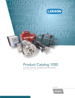
Gearmotors
Right-Angle - AC Gearmotors
Output Torque - 14-113 In-Lbs
Features:
• Permanent split capacitor design rated for 115/230VAC 60/50 HZ input
• Worm-type right-angle gearing features hardened, steel worm with bronze
worm wheel for long life and quiet operation
• Precision machined aluminum gear housing
• Lubrication is permanent with an oil bath
• Gearbox has all ball bearings
• Output shaft is field interchangeable from left hand to right hand style by reassembly
• Double output shaft available as a factory option
• Optional conduit box available, see page 342
• Optional gearbox base available (10 Series only), see page 342
Application Notes:
• These right-angle gearmotors have a lubrication breather positioned for horizontal mounting. For
other mountings, the breather plug must be reoriented by using a 90 deg 1/8” NPT taper pipe
elbow (See drawing). Elbow not available from LEESON
• These gearmotors are designed for mounting at any angle, but motor below the reducer should be
avoided to prevent leakage of lubricant into the motor should the motor shaft seal fail
• Overhung load capacities shown are at center of output shaft
• Continuous duty run capacitor supplied as standard
• For additional information, see Bulletin 1830
•
Bodine/Dayton direct interchange
Single Phase - 115/230 Volt - TEFC - Right-Angle
Y
Note listing on inside back flap
Output
RPM
F.L.
Torque
(Lb.In.)
Input
HP
Catalog
Number
List
Price
Model
Number
Gearmotor
Type &
Frame
Ratio
to 1
F.L.
Amps
@115V
Over-
hung
Load
(lb.)
Dimensions (inches)
Capacitor
Mfd. 240
VAC
Y
Notes
P X XL XH
28 37 1⁄15
M1125080.00√ 677 M31P17NZ19 10F60-31C 60 0.9 185 3.07 3.63 8.94 5.31 10.0¤ S, US, 12
43 34 1⁄15
M1125081.00√ 677 M31P17NZ18 10F40-31C 40 0.9 185 3.07 3.63 8.94 5.31 10.0¤ S, US, 12
58 40 1⁄15
M1125082.00√ 677 M31P17NZ17 10F30-31C 30 0.9 185 3.07 3.63 8.94 5.31 10.0¤ S, US, 12
85 24 1⁄15
M1125083.00√ 677 M31P17NZ16 10F20-31C 20 0.9 185 3.07 3.63 8.94 5.31 10.0¤ S, US, 12
173 14 1⁄15
M1125084.00√ 677 M31P17NZ15 10F10-31C 10 0.9 185 3.07 3.63 8.94 5.31 10.0¤ S, US, 12
29 110 1⁄6
M1145037.00√ 918 M38P17FZ16 13F60-38F 60 2.0 235 3.85 4.50 12.31 7.81 15.0¢ S, US, 13
43 113 1⁄6
M1145038.00√ 918 M38P17FZ17 13F40-38F 40 2.0 235 3.85 4.50 12.31 7.81 15.0¢ S, US, 13
57 95 1⁄6
M1145082.00√ 918 M38P17FZ23 13F30-38F 30 2.0 235 3.85 4.50 12.31 7.81 15.0¢ S, US, 13
83 75 1⁄6
M1145039.00√ 918 M38P17FZ18 13F20-38F 20 2.0 235 3.85 4.50 12.31 7.81 15.0¢ S, US, 13
170 43 1⁄6
M1145040.00√ 918 M38P17FZ19 13F10-38F 10 2.0 235 3.85 4.50 12.31 7.81 15.0¢ S, US, 13
340 23 1⁄6
M1145041.00√ 918 M38P17FZ20 13F05-38F 5 2.0 235 3.85 4.50 12.31 7.81 15.0¢ S, US, 13
Stock
¤ 250 VAC
¢ 300 VAC
Note 12 - TENV
Specifications are subject to change without notice