


 466 / 488

466
IEC Motors
DC Motors
Gearmotors
AC / DC Controls
Accessories / Kits
Mods / Factory
Options
X-Ref / Index
Tech Information
Terms / Warnings
Technical Information
MOTOR SELECTION
Electric motors are the workhorses of industry. Many applications exist
where more than one motor can be used and/or the exact replacement is
not available. LEESON makes every effort to maximize interchangeability,
mechanically and electrically, where compromise does not interfere with
reliability and safety standards. If you are not certain of a replacement
condition, contact any LEESON Authorized Distributor or the LEESON
District Sales Office.
SELECTION
Identifying a motor for replacement purposes or specifying a motor for new
applications can be done easily if the following information is known:
1. Nameplate Data 3. Electrical and Performance Characteristics
2. Motor Type
4. Mechanical Construction
NAMEPLATE DATA
Nameplate data is the most important first step in determining motor
replacement. Much of the information needed can generally be obtained
from the nameplate of the motor to be replaced. Take time to record all the
nameplate information because it can save time, avoid confusion and
MISAPPLICATION.
MOTOR TYPE
Alternating current (AC) induction motors are divided into two electrical
categories, based on power source—single phase and polyphase (three
phase). Direct current (DC) motors are used in applications where precise
speed control is required or when battery or generated direct current is the
available power source.
ELECTRICAL AND PERFORMANCE CHARACTERISTICS
One of the best ways to guarantee economical performance and long
motor life is to make sure your motors operate at nameplate voltage.
Applying too high a voltage may reduce the motor’s efficiency and
increase operating temperatures. The net result is shorter motor life.
Under-voltage can also shorten motor life. Operating on too low a voltage
reduces the motor’s effective horsepower. The motor will attempt to drive
the load it was intended to drive, become overloaded, draw more current
than normal, and overheat. Again, the result will be premature failure.
ENCLOSURES AND ENVIRONMENT
DRIP-PROOF:
Venting in end frame and/or main frame located to pre-
vent drops of liquid from falling into motor within a 15˚ angle from vertical.
Designed for use in areas that are reasonably dry, clean, and well ventilated
(usually indoors). If installed outdoors, it is recommended that the motor be
protected with a cover that does not restrict the flow of air to the motor.
TOTALLY ENCLOSED AIR OVER (TEAO):
Dust-tight fan and blower duty
motors designed for shaft mounted fans or belt driven fans. The motor must
be mounted within the airflow of the fan.
TOTALLY ENCLOSED NON-VENTILATED (TENV):
No vent openings,
tightly enclosed to prevent the free exchange of air, but not airtight. Has
no external cooling fan and relies on convection for cooling. Suitable for
use where exposed to dirt or dampness, but not for hazardous (explosive)
locations.
TOTALLY ENCLOSED FAN COOLED (TEFC):
Same as the TENV except
has external fan as an integral part of the motor, to provide cooling by
blowing air around the outside frame of the motor.
TOTALLY ENCLOSED, HOSTILE AND SEVERE ENVIRONMENT
MOTORS:
Designed for use in extremely moist or chemical environments,
but not for hazardous locations.
TOTALLY ENCLOSED BLOWER COOLED MOTORS (TEBC):
Used to
extend the safe speed range of inverter-fed motors. Similar to TEFC except
a small, constant-speed fan provides uniform airflow regardless of the drive
motor’s operating speed.
EXPLOSION-PROOF MOTORS:
These motors meet Underwriters
Laboratories and Canadian Standards Association standards for use in
hazardous (explosive) locations, as indicated by the UL label affixed to the
motor. Locations are considered hazardous because the atmosphere does
or may contain gas, vapor, or dust in explosive quantities.
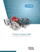
TYPICAL SPEED TORQUE CURVES
Capacitor Start/Induction Run
A single phase general purpose design, with an
electrolytic capacitor in series with the start winding,
offering maximum starting torque per ampere.
A centrifugal switch removes the auxiliary winding
and capacitor when the motor approaches full
load speed. The design is a heavy-duty unit which
has approximately 300% (of full load) starting
torque. Common applications include compres-
sors, pumps, conveyors and other “hard-to-start”
applications.
Capacitor Start/Capacitor Run
This design has two capacitors of different values. A centrifugal switch is
used to remove the electrolytic capacitor when the motor approaches full
load speed. A second run capacitor remains in series with the auxiliary wind-
ing during full load operation. This type of design has lower full-load amps
as a result of the run capacitor and is consequently used on most higher
horsepower single phase motors.
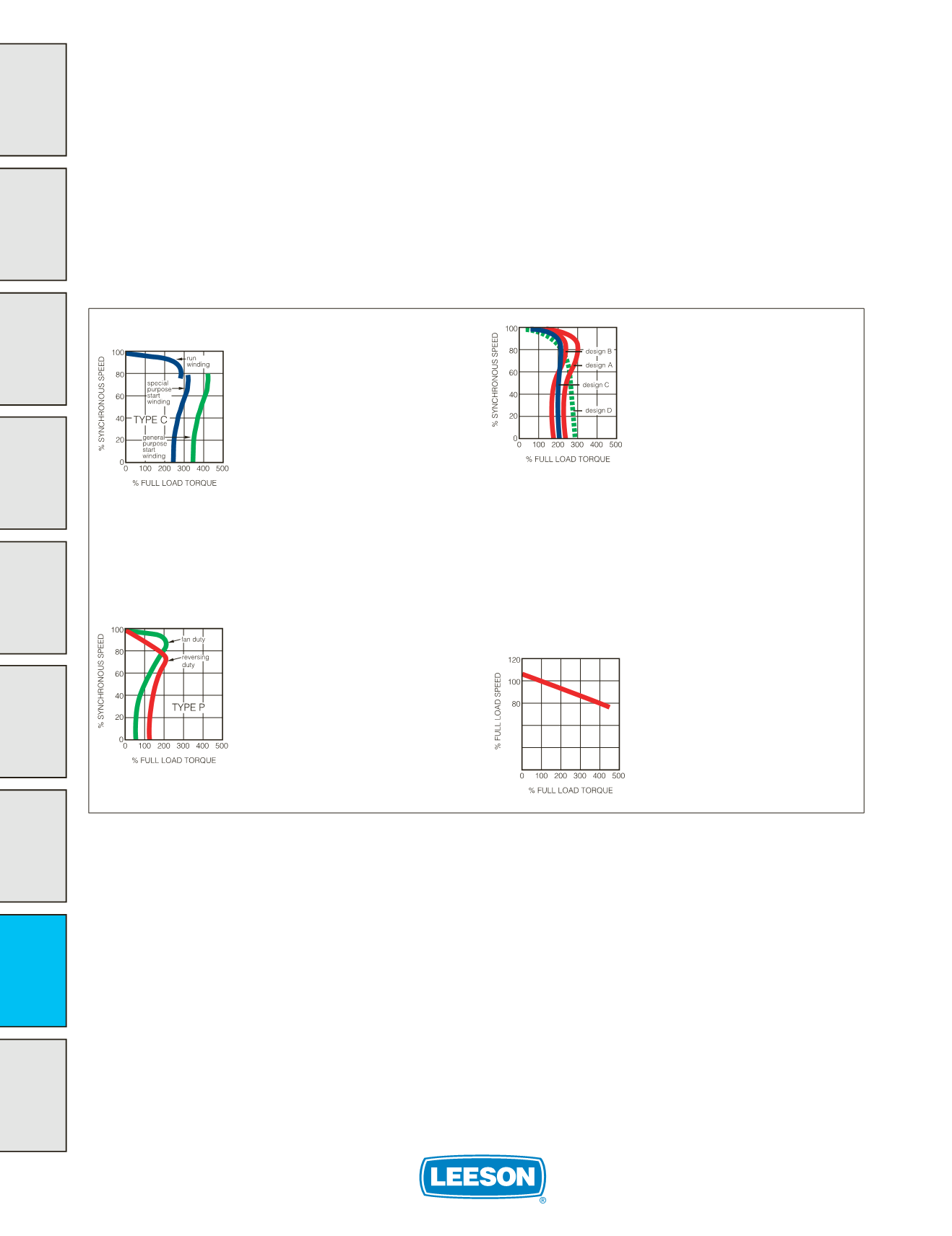
Permanent Split Capacitor (PSC)
This design has an auxiliary winding with a
“run” capacitor, but unlike the capacitor start/
induction run motor, the capacitor and auxiliary
winding remain in the circuit under running condi-
tions. (There is no centrifugal switch on this type
motor.) A permanent split capacitor design has low
starting torque and low starting current. They are
generally used on direct-drive fans and blowers.
They can also be designed for higher starting
torque and intermittent applications, where rapid
reversing is desired.
Three Phase or Polyphase
General purpose three phase motors have
different electrical design classifications as
defined by NEMA. NEMA Design A and B
motors are of normal starting torque with
normal starting current. NEMA Design C
motors have higher starting torque with
normal starting current. All three types have
slip of less than 5%. (“Slip” being a term
which expresses, as a percentage, the dif-
ference between synchronous motor speed
and full load motor speed, for example, 1800
rpm synchronous versus a full load speed of
1740 rpm.
NEMA’s Design B and C standards are minimum performance standards.
In practice, some manufacturers (including LEESON) build small integral
HP Design B motors with locked rotor and breakdown torque levels equal-
ling NEMA Design C standards.
NEMA T frame motors 1 through 200 HP
covered
by EPAct (identified
with a “G” catalog prefix) are labeled Design B, exceed NEMA Design
B performance levels, and have efficiencies equal to EPAct mandated
levels. EPAct
exempt
three phase, base-mounted motors are labeled
Design C and have performance characteristics meeting NEMA’s Design
C standards, with standard motor efficiencies. Motors 250 HP and
larger are exempt from EPAct legislation.
Permanent Magnet DC
This design has linear speed/torque
characteristics over the entire speed range.
SCR rated motor features include high start-
ing torque for heavy load applications and
dynamic braking, variable speed and reversing
capabilities. Designs are also available for
use on generated low voltage DC power or
remote applications requiring battery power.