


 133 / 184

CVPDC-0914
TECHNICAL AND PERFORMANCE DATA
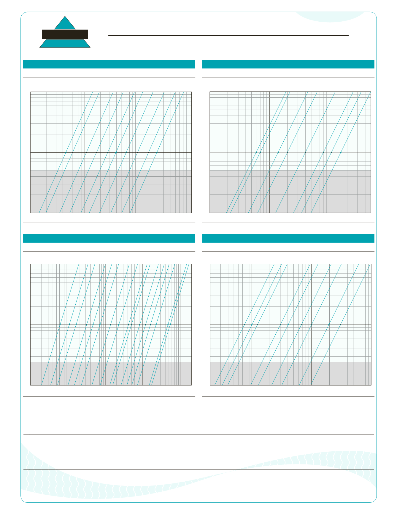
PRESSURE DROP CHARTS
f
CHECK VALVES
TITAN
TITAN FLOW CONTROL, INC.
Style: Threaded Ends, Silent CheckValve
Style: Threaded Ends, Silent CheckValve
Model: CV 20-BZ (Bronze Unit)
Model: CV 80-SS (Stainless Steel Unit)
Legend: Pressure Drop - PSI (y - axis) versus Flow Rate - GPM (x - axis)
Legend: Pressure Drop - PSI (y - axis) versus Flow Rate - GPM (x - axis)
Style: WaferType, Single Disc CheckValve
Style: WaferType, Short Pattern, Swing CheckValve
Models: CV 31-DI, CV 32-CS/SS
Models: CV 12-CS/SS
Legend: Pressure Drop - PSI (y - axis) versus Flow Rate - GPM (x - axis)
Legend: Pressure Drop - PSI (y - axis) versus Flow Rate - GPM (x - axis)
Pressure Drop Equation for Liquids:
Δ P = G × (Q / Cv)
2
Δ P = Pressure drop (psi)
G = Specific gravity of liquid at 60 °F
Cv = Flow coefficient factor
Q = Flow rate (GPM)
0.2
0.3
0.4
0.5
0.7
1
2
3
4
5
6
7
10
1
0.1
2 3 4 5 6 7 8 10
20 30 40 50 70 100
200 300 500 700 1000
3/8
1/4
1/2
3/4
1
1 1/4
1 1/2
2
2 1/2
3
4
Sizes (in):
C v
C v
5
6
11
17
27
39
61
98
158
225
Valve Cracking Pressure (0.5 psi)
(Horizontal Position)
0.2
0.3
0.4
0.5
0.7
1
2
3
4
5
6
7
10
1
0.1
2 3 4 5 6 7 8 10
20 30 40 50 70 100
200 300 400 500
3/8
1/2
3/4
1
1 1/4
1 1/2
2 1/2
3
2
C v
C v
6
7
14
20
40
80
110
162
Sizes (in):
Valve Cracking Pressure (0.5 psi)
(Horizontal Position)
0.2
0.3
0.4
0.5
0.7
1
2
3
4
5
6
7
10
10
0.1
20 30 50 70 100 200 300 500 1000 2M 5M 10M 20M 50M 100M 200M
Sizes (in):
C v
C v
62
109
166
318
471
720
1384
2298
4153
4984
8307
11906
16059
22705
47071
53993
2
2 1/2
3
4
5
6
8
10
12
14
16
18
20
24
30
36
Valve Cracking Pressure (0.25 psi)
(Horizontal Position)
30 40 50 70 100
200 300 500 700 1000
2M 3M 5M 7M 10M
20
0.1
0.2
0.3
0.4
0.5
0.7
1
2
3
4
5
6
7
10
C v
C v
75
100
124
300
405
675
1000
1950
3050
2
2 1/2
3
4
5
6
8
10
12
Sizes (in):
Valve Cracking Pressure (0.25 psi)
(Horizontal Position)
Tel: 910-735-0000
s
Fax: 910-738-3848
s
titan@titanfci.coms
www.titanfci.com290 Corporate Drive
s
PO Box 7408
s
Lumberton, NC 28358
TITAN FLOW CONTROL, INC.
•
These curves are theoretical; actual results may vary depending on installation conditions and other variables. Use these values for reference only.
•
The above pressure drop charts are based upon 1/8" perforated screens and baskets handling clean water at 60 °F during ideal inlet and outlet conditions. Therefore, they
should only be used for estimation purposes.
•
For fluids other than water, multiply the pressure drop (Δ P) obtained from the charts by the specific gravity of the fluid in question.
•
For mesh lined screens, multiply the pressure drop (Δ P) obtained from the charts by the corresponding correction factor shown in the Cv correction table.