


P
E
P
RODUCT MPHASIS ROGRAM
1
The Hydraulic Brake System
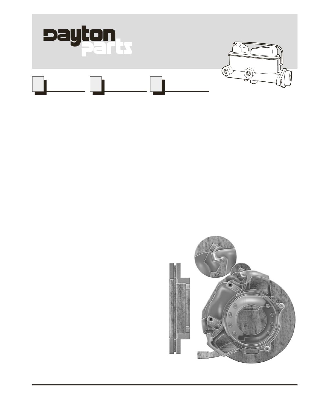
Typical Hydraulic Disc Brake & Rotor
In the medium duty truck market, the preferred brake system is a four wheel hydraulic disc. Dayton Parts
carries a complete line of components from the master cylinder (the beginning) to the rotor (the end). Some
applications still use hydraulic drum brakes but since that is such a small percentage of today's market, we'll
focus on the hydraulic disc.
The main function of a brake system is to slow the vehicle down to a safe and progressive stop. This is
accomplished with a delivery agent, in this case hydraulic fluid, and a way to create work or pressure, the
master cylinder. When the operator applies the brake pedal, the pressure created in the master cylinder is
transferred through the brake hoses/steel lines to a component, in this case the caliper, that will apply this
pressure to the wheel assembly.
The pressure from the master cylinder causes the piston(s) in the caliper to push out the inner pad of friction
material and at the same time the caliper slides so as to center both the inner and outer pads on the rotor. The
pads of friction material squeeze both sides of the rotor,
which is machined with a slight waver in it, and causes
the rotor to slow down rotation. The friction material
accomplishes this by changing the kinetic energy of
the rotating wheel assembly into heat and releasing
it into the atmosphere.
The rotor is attached to the hub/wheel assembly
on the end of the axle. The hub/wheel assembly
has the tires mounted to it to transfer the
slowing down of the assembly to the ground
(pavement) and thereby slowing the vehicle
itself.
Now that we have done a brief overview of how
the hydraulic brake system works let's take a
look at the individual components inside the
system.
TM
PEP Program No. 12
March, 2002
www.daytonparts.comHydraulic
Brake