


 15 / 31


356
T
hiex
:
J
ournal of
AOAC I
nternational
V
ol
.
99, N
o
.
2, 2016
V = Volume (in mL) of respective extract collected.
W = Total unground test portion weight in g.
Calculations.
—(An example calculation is provided in ref. 1.)
%AR
AC , mg
L
1 g
1000 mg
V, mL 1000 mL
W, g A , g
100 g
100
x
x
ex
ex
t
=
×
×
×
×
(
)
(
)
( )
G. Expression of Results
Results for each extraction are presented as cumulative
percentage of total nutrient. Extraction 1 (7 days) is considered
water-soluble and not an SRF. However, slowly available
water-soluble materials (low-MW urea formaldehydes and
methylene ureas) may be present. These materials can be
analyzed directly from Extract 1.
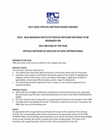
Graphing release plots.
—Plot the cumulative % of analyte
(nutrient) released on the
y
-axis versus days of extraction on
the
x
-axis as in Figure
2015.15B
. (The example calculations are
provided in ref. 1.)
Alternative B: Accelerated 74 h
Extraction at 25–60°C
H. Apparatus
(a)
Covered water bath capable of maintaining a
temperature of up to 60°C for extended periods. Ensure the
mean temperature in the system is 50.0, 55.0, or 60.0 ± 1.0°C
by monitoring incoming and exit temperatures to the manifold
at comparable locations. Before Extractions 2–4 begin, it is
necessary to preheat the bath several degrees (
see Extraction
section below) above the desired temperature to account
for initial heat exchange and temperature equilibration with
manifold and columns. The bath should be stabilized at the
desired temperature within 10 min.
(b)
Reversible peristaltic pump capable of delivering
4.0 (±0.1) mL/min continuously for 54 h. Pump heads capable
of using 16–40 tubes are used for an 8–20 column apparatus,
respectively (Lsmatc
®
No. 78006–00; Cole-Parmer, Vernon
Hills, IL).
(c)
Extraction apparatus consisting of two parts (illustrated
in Figures
2015.15C
–
F
). Example equipment with sources can
be found as a parts list in Appendix A of ref. 2 available on the
J. AOAC Int
. web site.
(d)
Vertical jacketed chromatography columns enclosing
inner column of 2.5 × 30 cm (e.g., No. 5821–24, filter removed,
with Teflon adapter No. 5838–51; Ace Glass, Vineland, NJ).
PTFE rods (6 mm × 15 cm) should be used to avoid channeling
of air or caking. Assure all fittings attaching column, pump
tubes, and transfer tubing are secure to avoid leaks. Standardize
the length of tubing for each column (typically about 75 cm).
Example equipment with sources can be found as a parts list
in Appendix A of ref. 2 available on the
J. AOAC Int
. web site.
(e)
Constant temperature water circulation manifold and
pump system capable of maintaining adequate (minimum
4 L/min) flow and stable temperature for each column.
Insulation is typically required to maintain a stable
temperature. Two inline, symmetrically placed thermometers
(Figure
2015.15E
) are used to monitor temperature to input
and outflow of manifolds. Attach roll clamps and flow
monitors to column manifold tubing to ensure balanced flows
and uniform temperatures. Example equipment with sources
can be found as a parts list in Appendix A of ref. 2 available on
the
J. AOAC Int
. web site.
(f)
Solvent/extract reservoirs [500 mL volumetric flasks
(e.g., Cat. No. 28100–500; Kimball Chase Life Science,
Vinland, NJ)] with three-hole stoppers and properly placed
rigid tubing attached to transfer tubing and to pump (
see
Figure
2015.15E
). Ensure return tube remains approximately
2 cm from the bottom of the flask to prevent pickup of any
precipitates.
Figure 2015.15D. Schematic diagram of water manifold used in the
extraction apparatus.
Figure 2015.15C. Extraction apparatus with eight jacketed
chromatography columns.
Figure 2015.15B. Example release plot showing % N released over
180 days.