


 9 / 88

1
7
Transformers + Substations Handbook: 2014
Core loss W/kg
Flux direction
0° 45° 90°
90°
45°
0°
45°
Lamination
Direction of rolling
5
4
3
2
1
1.7 T
1.5 T
1.3 T
1 T
Figure 3: Losses in grain orientated lamination steel for various directions
of magnetisation [1].
The purpose of the core steel is to provide a low reluctance path for
the magnetic flux that links the primary and secondary windings.
Lamination steel is specifically designed to reduce losses in the
steel. There are two main components to iron losses they are:
• Hysteresis losses
• Eddy current losses
Hysteresis is dependent on frequency, material and flux density. Eddy
current is dependent on the square of the frequency and the square of
the material thickness.
A number of different grades and types of lamination steel are
available.
• Hot rolled steel
• High-permeability steel (0,025% Al cold rolled) (30 to 40%)
• Domain-refined steel (5 to 8%)
• Amorphous steel (80% Iron 20% Boron and Silicon) (33,33% im-
provement at knee point) (1,5 to 1,6 Tesla)
Core profile can be square, round (stepped), oval or rectangle. The joint
can also take on many configurations (butt, overlap, mitred, etc).
Core-magnetic circuit
The magnetic flux density is measured in Tesla (Webers/m
2
), and
normal values for a transformer range between 1,6 and 1,8 Tesla.
How eddy currents are avoided in the core (eddy currents
increase no-load losses and create hot-spots):
• The core steel laminations should be thin
• The core steels should be insulated from each other
• Smallest burrs possible in both slitting and cutting as these burrs
create shorts across the laminations
• The core steel should have high resistivity
Joint between core laminations:
• In joints the magnetic flux ‘jumps’ to the adjacent laminations, with
local saturation as a result
• Step-lap joints have a higher saturation limit compared with con-
ventional joints. The magnetising current is lower for the step-lap
in this area of the joint
• Mechanically, the step-lap joint is weaker than the conventional
joint because of the smaller overlap
• It is important to keep the gap between the laminations as small
as possible at the joints
• The clamping at the joint must be as strong as possible to reduce
noise, increase strength and reduce gap losses
To summarise:
Step-lap
+ Lower losses
+ Lower noise level
- Mechanical strength
Conventional
+ Mechanical strength
- Higher losses
- Noise level
Area of
higher flux
concentration
Step-lap
joint
Conventional
joint
Figure 4: Lamination joints.
• The core construction can take on many forms but must be rigid
and tightly clamped
• All clamping must be insulated to eliminate the possibility of circu-
lating currents as a result of the main flux and or the leakage
fluxes
• Clamping must not short-out the lamination; through bolts must
be insulate
Windings
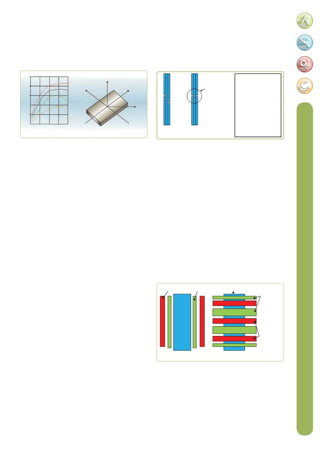
Winding can be done in a number of configurations, namely concentric
or sandwich types. In the concentric type the LV coil is generally wound
against the core and the HV winding over the LV winding. In certain
applications the HV is against the core and the LV is in on the outside.
The sandwich type of winding is assembled with alternating low and
high voltage winding.
HV winding
Concentric type winding Sandwich type winding
LV winding
LV windings
HV windings
Core
Core
Figure 5: Winding types.
There are four types of coils used in transformer winding assemblies
- cylindrical (
Figure 6
), bobbin (
Figure 7
), disc (
Figure 8)
and foil windings
(
Figure 9
).
• Foil-type winding: Foil wound transformers generally have the LV
wound using aluminium or copper foil over the full width of the
winding; therefore with one turn per layer and the number of turns
equal to the number of layers, the foil being wound with a suitable
insulation is interleaved with the foil.
In its simplest form, a transformer
consists of two conducting coils having
a mutual inductance