


 10 / 40

8
Chemical Technology • January 2015
Control & Instrumentation
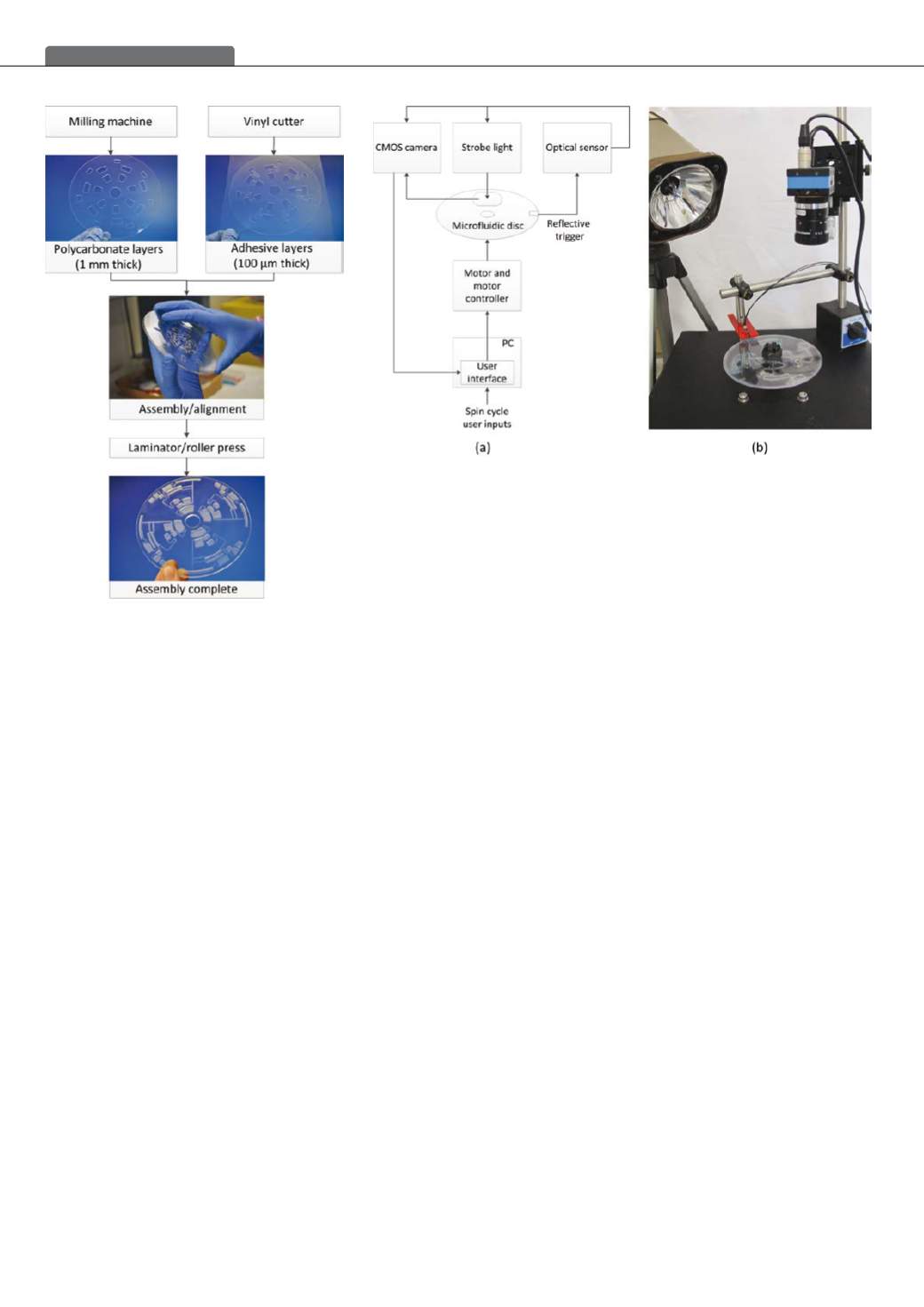
the microfluidic disc to be tested to allow the transmitted
light from the optical sensor to be reflected into the receiver
of the optical sensor, in turn triggering the camera to capture
an image, and triggering the strobe light to illuminate the
region of interest on the microfluidic disc, ensuring that a
clear still image was captured.
The user controls the rotation of the microfluidic disc
or spin cycle via a user interface on a PC. The user can
program the speed, acceleration, deceleration and tim-
ing cycles of the disc to automate fluidic functions on the
microfluidic disc.
Platform and scale-up costs
Excluding the equipment, which was already available in-
house, the costs to produce a complete centrifugal micro-
fluidic system amounted to R25 000. The cost of materials
for the disc devices amounted to R500/m
2
and R10 per
prototype disc device.
A comparison of system integration criteria for various
microfluidic technologies [16] shows that centrifugal mi-
crofluidic systems rank highly as viable, low-cost solutions
for integrated lab-on-a-disc systems [16]. Although the
lab-on-a-disc system is in the early stages of development,
scale-up of the system is an ongoing consideration. Scale-
up will continue to be considered and developed based on
the desired end application of the system.
To ensure the successful development of the lab-on-
a-disc system into a viable medical diagnostic product,
medical device regulatory requirements will be an important
consideration. Role players in the regulatory environment
are currently being engaged to determine the requirements
for the South African market.
Results
Initial applications of the complete centrifugal microfluidic
platformwere implemented to illustrate the process carried
out from design to analysis of a lab-on-a-disc system. The
first example demonstrates basic fluidic functions on the
disc such as introduction, valving and combining of fluids,
and illustrates potential diagnostic applications for ma-
nipulation of biological samples such as blood. The second
example demonstrates microfluidic droplet generation using
the centrifugal microfluidic platform.
Basic fluidic functions
To demonstrate basic fluidic functions, a simple microfluidic
disc design was formulated to allow for a sample and a
sample reagent to be introduced separately, added together
at different times, and combined, with an overflow chamber
for excess solution. For the purposes of illustration, a yeast
solution was used to simulate blood, while the reagent was
a staining solution commonly used to stain blood cells for
visualisation and performing manual blood cell counting.
The use of a yeast solution as a proxy also allowed the
sedimentation or separation of particles in fluids to be il-
lustrated by the centrifugal microfluidic system.
Figure 3 on page 10 shows the microfluidic features of
the disc design used to achieve the desired fluidic func-
tions. Four identical microfluidic systems were designed
and manufactured on one disc. The microfluidic channels
are 1 mmwide and 100 µm deep, while the chambers have
a depth of 1,2 mm and vary in width and length. The vent
holes have a diameter of 1 mm.
The blood simulant solution was made from 10 mg dry
baker’s yeast in 100 m
l
deionised water to yield a similar
concentration of cells to that of white blood cells found in a
human blood sample. The staining reagent was a 2 % acetic
acid solution with 1 mg crystal violet in 100 m
l
deionised
water – a standard white blood cell reagent commonly used
to lyse red blood cells and stain the nuclei of white blood
cells for manual white blood cell counting.
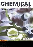
Figure 1: Illustration of microfluidic disc manufacture
and assembly process
Figure 2: (a) Schematic of the components required for fluidic control and imaging of the disc
device and (b) the integrated testing system set-up