


 6 / 24

sparks
ELECTRICAL NEWS
june 2015
ACCORDING to the South African Photovoltaic In-
dustry Association (SAPVIA), PV is the fastest grow-
ing power generation technology in the world.
Between 2006 and 2009 the installed capacity
globally grew on average by 60% p a. Today, more
than 35 GWof PVs have been installed and are
operating worldwide, producingmore than
30 TWh of clean energy per year.
Bearing inmind that self-generated electricity
is generally cheaper and provides a high degree
of electrical independence from the grid, PV
systems will become an integral part of electrical
installations in the future. However, these systems
are exposed to all weather conditions andmust
withstand themover decades. The cables of PV
systems frequently enter the building in question
and extend over long distances until they reach
the grid connection point.
Lightning discharges cause field-based and
conducted electrical interference. This effect
increases in relation to increasing cable lengths
or conductor loops. Surges do not only damage
the PVmodules, inverters and their monitoring
electronics, but also devices in the building instal-
lation. More importantly, production facilities of
industrial buildings may also be damaged and
halt production.
If surges are 'injected' into systems that are far
from the power grid – which are also referred
to as stand-alone PV systems – the operation of
equipment powered by solar electricity, such as
medical equipment, water supply, and so on, may
be disrupted.
Necessity of a rooftop lightning protection
system
The energy released by a lightning discharge is
one of the most frequent causes of fire. Therefore,
personal and fire protection is of paramount
importance in case of a direct lightning strike to
a building.The installation of PVmodules does
increase the risk of lightning strikes as the col-
lection area increases and substantial lightning
interference may be injected into the building
through these systems. Therefore, it is necessary to
determine the risk resulting from a lightning strike
as per IEC 62305-2 (SANS 62305-2) and to take the
results from this risk analysis into account when
installing the PV system. For this purpose, DEHN,
for example, offers a service through its consulting
division, DEHNconcept, which can conduct the
risk analysis and design a lightning protection
system (LPS) for the site.
These standards require that a lightning
protection system according to class of LPS III be
installed for rooftop PV systems (> 10 kWp) and
that surge protectionmeasures are taken.
As a general rule, rooftop PV systems must not
interfere with the existing lightning protection
measures.
Necessity of surge protection for PV systems
In case of a lightning discharge, surges are induced
on electrical conductors. Surge protective devices
(SPDs), whichmust be installed upstreamof the
devices to be protected on the alternating current
(ac), direct current (dc) and data side, have proven
effective in safeguarding electrical systems from
these destructive voltage peaks. Section 9.1 of the
CLC/TS 50539-12 standard (Selection and applica-
tion principles – SPDs connected to photovoltaic
installations) calls for the installation of surge pro-
tective devices unless a risk analysis demonstrates
that SPDs are not required.
According to IEC 60364-4-44, surge protective
devices must also be installed for buildings with-
out external lightning protection systems such as
commercial and industrial buildings.
Cable routing of PV systems
Cables must be routed in such a way that large
conductor loops are avoided. This must be ob-
served when combining the dc circuits to form a
string and when interconnecting several strings.
Moreover, data or sensor lines must not be routed
over several strings and form large conductor
loops with the string lines. This must also be ob-
served when connecting the inverter to the grid
connection. For this reason, the power (dc and ac)
and data lines must be routed together with the
equipotential bonding conductors along their
entire route.
Earthing of PV systems
PVmodules are typically fixed onmetal mounting
systems. The live PV components on the dc side
feature double or reinforced insulation (compara-
ble to the previous protective
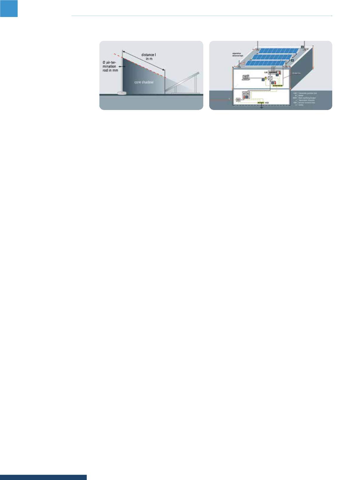
A building with external protection system and sufficient separation distance.
Lightning and surge protection for rooftop photovoltaic (PV) systems
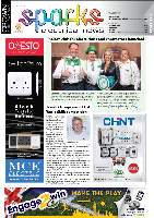
The distance between the module and the air termination rod required to prevent shadows.
insulation) as required in IEC 60364-4-41. The
combination of numerous technologies on the
module and inverter side, with or without galvanic
isolation, results in different earthing require-
ments. Moreover, the insulationmonitoring sys-
tem integrated in the inverters is only permanent-
ly effective if the mounting system is connected
to earth. The metal substructure is functionally
earthed if the PV system is located in the protect-
ed volume of the air termination systems and the
separation distance is maintained.
International guidelines require copper con-
ductors, with a cross-section of at least 6 mm
2
or equivalent, be used for functional earthing.
The mounting rails also have to be permanently
interconnected by means of conductors of this
cross-section. If the mounting system is directly
connected to the external lightning protec-
tion system, due to the fact that the separation
distance cannot be maintained, these conductors
become part of the lightning equipotential bond-
ing system. Consequently, these elements must
be capable of carrying lightning currents.
The minimum requirement for a lightning
protection systemdesigned for class of LPS III is a
copper conductor with a cross-section of 16 mm
2
or equivalent. Also in this case, the mounting rails
must be permanently interconnected by means
of conductors of this cross-section. The functional
earthing / lightning equipotential bonding con-
ductor should be routed in parallel and as close as
possible to the dc and ac cables / lines.
UNI earthing clamps can be fixed on all com-
monmounting systems. They connect, for exam-
ple, copper conductors with a cross-section of six
or 16 mm
2
and bare round wires with a diameter
from eight to 10 mm, to the mounting frame in
such a way that they can carry lightning currents.
The integrated stainless steel (V4A) contact plate
ensures corrosion protection for the aluminium
mounting systems.
Separation distances as per IEC 62305-3
(EN 62305-3)
A certain separation distance must be maintained
between a lightning protection system and a PV
system. It defines the distance required to avoid
uncontrolled flashover to adjacent metal parts
resulting from a lightning strike to the external
lightning protection system. In the worst case,
such an uncontrolled flashover can set a PV plant
on fire.
The calculation of the separation distance can
be easily and quickly calculated by an analysis
package, such as the DEHNconcept, for example.
Core shadows on solar cells
The distance between the solar generator and the
external lightning protection system is absolutely
essential to prevent excessive shading. Diffuse
shadows cast by, for example, overhead lines,
do not significantly affect the PV system and the
yield. However, in case of core shadows, a dark
clearly outlined shadow is cast on the surface
behind an object, changing the current flowing
through the PVmodule. For this reason, solar cells
and the associated bypass diodes must not be
influenced by core shadows. This can be achieved
by maintaining a sufficient distance. For example,
if an air-termination rod with a diameter of 10 mm
shades a module, the core shadow is steadily re-
duced as the distance from the module increases.
After 1.08 monly a diffuse shadow is cast on the
module.
Special surge protective devices (SPD) for
the dc side of photovoltaic systems
The U/I characteristics of photovoltaic current
sources are very different from that of
conventional dc sources: They have a non-linear
characteristic and cause long-termpersistence
of ignited arcs. This unique nature of PV current
sources does not only require larger PV switches
and PV fuses, but also a disconnector for the surge
protective device, which is adapted to this unique
nature and capable of coping with PV currents.
Selection of SPDs according to the voltage
protection level Up
The operating voltage on the dc side of PV systems
differs from system to system. At present, values
up to 1 500 V dc are possible. Consequently, the
dielectric strength of terminal equipment also
differs. To ensure that the PV system is reliably
protected, the voltage protection level up of the
SPDmust be lower than the dielectric strength of
the PV system it is supposed to protect. The CLC/TS
50539-12 standard requires that Up is at least 20%
lower than the dielectric strength of the PV system.
Type 1 or Type 2 SPDs must be energy-coordinated
with the input of terminal equipment.
If SPDs are already integrated in terminal equip-
ment, coordination between the Type 2 SPD and
the input circuit of terminal equipment is ensured
by the manufacturer.
Application example 1: Buildingwithout
external lightning protection system
In a building without external lightning protection
system, dangerous surges enter the PV systemdue
to inductive coupling resulting fromnearby light-
ning strikes or travel from the power supply system
through the service entrance to the consumer’s
installation. Type 2 SPDs are to be installed at the
following locations:
• Dc-side of the modules and inverters;
• Ac output of the inverter;
• Main low-voltage distribution board; and
• Wired communication interfaces.
Every dc input (MPP) of the inverter must be
protected by a Type 2 surge protective device.
European standards require that an additional
Type 2 dc arrester be installed on the module side
if the distance between the inverter input and the
PV generator exceeds 10 m.
The ac output of the inverters are sufficiently
protected if the distance between the PV inverters
and the place of installation of the Type 2 arrester
at the grid connection point (low-voltage infeed) is
less than 10 m. In case of greater cable lengths, an
additional Type 2 surge protective device must be
installed upstreamof the ac input of the inverter.
Moreover, a Type 2 surge protective device must
be installed downstreamof the meter of the low-
voltage infeed.
If inverters are connected to data and sensor
lines tomonitor the yield, suitable surge protective
devices are required.
Application example 2: Buildingwith
external lightning protection systemand
sufficient separation distances
In this case, the primary protection goal is to avoid
damage to persons and property (building fire)
resulting from a lightning strike. Here it is impor-
tant that the PV systemdoes not interfere with
the external lightning protection system. Moreo-
ver, the PV system itself must be protected from
direct lightning strikes. This means that it must be
installed in the protected volume of the exter-
nal lightning protection system. This protected
volume is formed by air-termination systems,
such as air-termination rods, which prevent direct
lightning strikes to the PVmodules and cables. The
protective angle method or rolling sphere method
may be used to determine this protected volume.
A certain separation distance must be main-
tained between all conductive parts of the PV
system and the lightning protection system.
In this context, core shadows must be prevented
by, for example, maintaining a sufficient distance
between the air-termination rods and the PV
module.
Lightning equipotential bonding is an integral
part of a lightning protection system. It must be
implemented for all conductive systems and lines
entering the building whichmay carry lightning
currents. This is achieved by directly connecting
all metal systems and indirectly connecting all
energised systems via Type 1 lightning current ar-
resters to the earth-termination system. Lightning
equipotential bonding should be implemented
as close as possible to the entrance point into the
building to prevent partial lightning currents from
entering the building.
The grid connection point must be protected
by a multi-pole spark-gap-basedType 1 SPD. If the
cable lengths between the arrester and inverter
are less than 10 m, sufficient protection is pro-
vided. In case of greater cable lengths, additional
Type 2 surge protective devices must be installed
upstreamof the ac input of the inverters.
Every dc input of the inverter must be protected
by a Type 2 PV arrester. This also applies to trans-
formerless devices. If the inverters are connected
to data lines, for example tomonitor the yield,
surge protective devices must be installed to
protect data transmission.
Another possibility tomaintain the separation
distance is to use high-voltage-resistant, insulated
HVI conductors, whichmaintain a separation
distance up to 0.9 m in the air. HVI conductors may
directly contact the PV systemdownstreamof the
sealing end range.
Application example 3: Buildingwith
external lightning protection systemwith
insufficient protection distance
If the roofing is made of metal or is formed by the
PV system itself, the separation distances cannot
be maintained. The metal components of the
PVmounting systemmust be connected to the
external lightning protection system in such a
way that they can carry lightning currents (copper
conductor with a cross-section of at least 16 mm
2
or equivalent). This means that lightning equipo-
tential bondingmust also be implemented for the
PV lines entering the building from the outside.
Lightning equipotential bondingmust also be
implemented in the low-voltage infeed. If the PV
inverter(s) is (are) situatedmore than tenmetres
from theType 1 SPD installed at the grid con-
nection point, an additionalType 1 SPDmust be
installed on the ac side of the inverter(s). Suitable
surge protective devicesmust also be installed to
protect the relevant data lines for yieldmonitoring.
PV systems withmicro-inverters
Micro-inverters require a different surge protec-
tion concept. To this end, the dc line of a module
or a pair of modules is directly connected to the
small-sized inverter. In this process, unnecessary
conductor loops must be avoided. Inductive cou-
pling into such small dc structures typically only
has a low energetic destruction potential.
The extensive cabling of a PV systemwith
micro-inverters is located on the ac side. If the
micro-inverters are directly fitted at the module,
surge protective devices may only be installed on
the ac side.
Conclusion
Solar power generation systems are an integral
part of today’s electrical systems. They should be
equipped with adequate lightning current and
surge arresters, thus ensuring the long-term fault-
less operation of these sources of electricity.
6
contractors’ corner