


 141 / 648


Safety and environmental standards for fuel storage sites
Final report
139
is the channel equivalent mean down time (in hours) resulting from a dangerous
failure (down time for all components in the channel of the subsystem)
is the voted group equivalent mean down time (in hours) resulting from a dangerous
failure of a channel in a subsystem (combined down time for all channels in the
voted group)
Example showing architectural influence on PFD
(avg)
45 To calculate the PFD
(avg)
for a complete SIF the failures all elements in the loop need to be
summed – the sensor, logic solver and final element
46 In the example below, the same instrumentation has been used but in two configurations to
achieve a minimum of SIL 1, 1oo1 and 1oo2.
47 The following assumptions have been made in order to calculate the PFD
(avg)
for the SIF:
The PFD
■
■
(avg)
value for the logic solver is fixed at 7.11 E-4.
The
■
■
b
factor for the undetected common cause failures is fixed at 2% (0.02).
The
■
■
b
D
factor for the detected common cause failures is fixed at 1% (0.01).
The proof test is a full, perfect proof test as opposed to a partial stroke test.
■
■
The mean time to repair (MTTR) is 8 hours for all elements.
■
■
Single devices comply to all requirements for use in a SIL 2 application.
■
■
The proof test provides 100% coverage factor for dangerous failure detection.
■
■
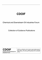
Figure 37
Typical tank overfill protection using 1oo1 architecture
48 Using the PFD
(avg)
calculations and the assumptions stated previously, the following values for
the PFD
(avg)
have been calculated for the 1oo1 architecture with a proof test interval of one year.
Sensor PFD
(1oo1)
3.03E-03
Logic Solver PFD
(1oo1)
7.11E-04
Valve PFD
(1oo1)
3.15E-05
Total loop PFD
(avg)
3.77E-03
t
CE
t
GE
MTTR
t
CE
t
GE
LT
Logic
solver
vent
Process
fluid
Storage tank
+
=
PFD
SYS
PFD
S
+
PFD
LS
PFD
FE