


 180 / 184

TITAN FLOW CONTROL, Inc.
290 Corporate Drive
E-mail:
titan@titanfci.comLumberton, NC 28358 Web:
www.titanfci.comTel: 910.735.0000
Fax: 910.738.3848
ANSI Class
150 lb
FOOT VALVE ASSEMBLY
FV 50-DI (Ductile Iron)
Flanged Ends • Globe Style • Center Guided Disc
DIMENSIONS AND PERFORMANCE DATA
(1)
SIZE
in
2
2
1
/
2
3
4
5
6
8
10
12
mm 50
65
80
100
125
150
200
250
300
A
DIMENSION
FACETO FACE
in
6.25
7.00
7.50
8.50
9.50 10.50 13.50 16.25 20.25
mm 159
178
191
216
242
267
343
413
515
B
DIMENSION
SCREEN LENGTH
in
3.00
3.00
3.00
3.00
4.00
5.00
6.00
7.00
8.00
mm
77
77
77
77
102
127
153
178
204
ØC
DIMENSION
SCREEN DIAMETER
in
6.00
7.00
7.50
9.00 10.00 11.00 13.50 16.00 19.00
mm 153
178
191
229
254
280
343
407
483
ØD
DIMENSION
BODY DIAMETER
in
4.625
5.75 6.625 8.625 10.00 11.125 15.84 17.687 21.25
mm 117
146
168
219
254
283
402
449
540
ASSEMBLED
WEIGHT
lb
25.0
35.0
36.5
61.0
76.0
91.5 180.0 265.0 411.0
kg
11.3
15.9
16.6
27.7
34.5
41.5
81.6 120.1 186.2
Flow Coefficient
C v
65
105
150
265
410
600 1100 1800 2500
Cracking Pressure
(2)
psi
≤ .5
≤ .5
≤ .5
≤ .5
≤ .5
≤ .5
≤ .5
≤ .5
≤ .5
FV50-0810
BILL OF MATERIALS
(1)
No. PART
FV 50-DI
1 Body
Ductile Iron ASTMA536
2 Disc
(2)
Cast Bronze ASTM B62
3 Spring
(2)
Series 300 Stainless Steel
4 Bushing
(2)
Cast Bronze ASTM B62
5 Seat
(2) (3)
Cast Bronze ASTM B62
6 Bolts
Stainless Steel
7 Screen
Type 304 Stainless Steel
1. Bill of Materials represents standard materials. Equivalent or better
materials may be substituted at the manufacturer's discretion.
2. Denotes recommended spare parts.
3. Resilient Seats (Buna-N) are available upon request.
TITAN
Titan FCI makes every effort to ensure the information presented on our literature accurately reflects exact product specifications. However, as product changes occur, there may be short-term differences between actual product
specifications and the information contained within our literature. Titan FCI reserves the right to make design and specification changes to improve our products without prior notification. When required, request certified drawings.
Additional Design &Technical Notes:
• The FV 50-DI is designed to fit Cast Iron ANSI
Class 125 and Ductile Iron ANSI Class 150
Flanges. The bolting pattern for Cast Iron
ANSI Class 125 and Ductile Iron ANSI Class
150 are identical.
• Ductile Iron body maintains the anti-
corrosive properties of Cast Iron while
achieving a yield strength comparable to
Carbon Steel. Ductile Iron also offers
higher pressure & temperature ratings
than Cast Iron.
• Screens are available in either basket
shaped or cone shaped. A wide variety
of perforations, meshes, and materials are
available for screens.
• Resilient seats (Buna-N) are available upon
request. Please contact factory.
1. Dimensions, weights, and flow coefficients are provided for reference only. When required, always request certified drawings.
2. Cracking pressure is for horizontal installations only. For vertical installations, please consult factory.
TEMPERATURE RANGE SEAT
SEAT
Temperature
Bronze
-460 °F @ 450 °F
MAXTEMPERATURE SPRING
SPRING
MaxTemperature
Stainless Steel
450 °F
PRESSURE -TEMPERATURE RATING
ANSI CLASS 150
ASTMA536
WOG
(Non-shock)
250 PSI @ 100 °F
The listed pressure and temperature ratings are theoretical
and may vary during actual operating conditions.
REFERENCED STANDARDS & CODES
CODE
DESCRIPTION
ANSI B16.42
Ductile Iron Pipe Flanges and Flanged Fittings
ANSI B16.5
Pipe Flanges & Flanged Fittings
MSS SP-6
Standard Finishes for Connecting-end Flanges
MSS SP-25
Standard Marking System for Valves
MSS SP-55
Quality Standard for Valve Castings
PRESSURE -TEMPERATURE RATINGS
(1)
Temperature (°F)
Pressure (PSI)
-50
50
150
250
350
450
550
650
0
50
100
150
200
250
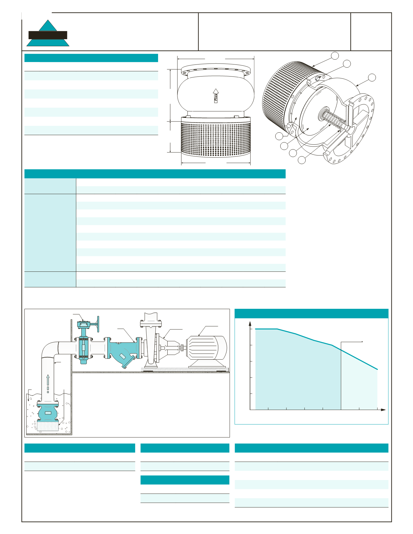
This chart displays the pressure-temperature
ratings for the valve’s body material per
ASME/ANSI B16.42-1998.
450 °F MaxTemp
Bronze Seat
SS Spring
1. This chart displays the pressure-temperature ratings for the valve's body.
Max temperature limits have been added for seat and spring materials.
C
Screen Diameter
A
Valve
Face-to-Face
B
Screen Length
D
Body Diameter
5
7
2
3
4
6
1
Wet
Well
Titan FCI
ButterflyValve
Titan FCI
WYE Strainer
Centrifugal
Pump
Pump
Motor
Titan
Titan
Titan
SIMPLIFIED ILLUSTRATION: FOOTVALVE INSTALLATION
A foot valve is a special type of check valve that has a built-in strainer. It is installed at the intake
side of a suction pipe and pump. Its purpose is to prevent the loss of prime when the liquid source
(wet well) is lower than the pump. Prime is defined as the charge of liquid required to begin
pumping action and priming is the process of filling the pump and suction pipe with liquid.
The check valve part of the foot valve opens when the pump starts to allow liquid to enter the
suction pipe and pump. When the pump stops,the check valve closes and prevents the liquid from
emptying. Thus the foot valve eliminates the need to prime the pump each time it is started. The
strainer component of the foot valve helps to remove unwanted debris from the liquid that may
cause damage to the pump.
In this type of installation,it is common to install a butterfly valve and a strainer on the suction side
of the pump. The butterfly valve is used to isolate the pump and the strainer provides additional
straining capacity.
Suction
Pipe
Titan FCI
FootValve
Sizes up to
24" available.
Call for information.