


 797 / 1003

RD-2-1325-0 (REV B)
Page 3
C. DRAIN HOSE INSTALLATION
1.
Route the drain tubes to the unit so that they travel in a downward direction from the unit.
2.
Cut off the
9
⁄
16
O.D. tubes to length and connect to fittings on unit. Secure drain tubes with tie wraps. Attach to
refrigeration hoses only if they run downhill properly.
3.
Red Wire: Connect to an ignition switch supply through a 30 amp circuit breaker (15amp/24V).
4.
White Wire: Connect to compressor clutch. Route the wire around the hinge point before connecting to compressor
clutch on tilt-cab installations.
D. WIRING
Note: a.
Unit is wired for negative ground.
For positive ground systems, reverse both motor leads on condenser motor and evaporator motor.
b.
Unit is internally grounded.
1.
Disconnect battery.
2.
Route red & white wire through 3⁄4 slot in plenum ring.
3.
Red Wire: Connect to an ignition switch supply through a 30 amp circuit breaker (15 amp/24V).
4.
White Wire: Connect to compressor clutch. Route the wire around the hinge point before connecting to compressor
clutch on tilt-cab installations.
E. AIR DIFFUSER PLENUM
1.
Install headliner. Make sure that wire loom exits plenum ring properly and is not pinched.
2.
Place one foam gasket in plastic plenum assembly. If headliner is over 1 inch thick, glue tow foam gaskets together.
An extra foam gasket may be ordered (part number RD-2-1297-0) if required.
3.
Place the plenum assembly up to the unit and start one M5 x 0.8 x 75mm screw.
4.
Attach the switch and thermostat to the plenum using 7⁄16–28 nuts (use two with switch, one with thermostat).
5.
Start the remaining three M5 x 0.8 x 75mm screws.
6.
Tighten the four plenum assembly screws evenly until the plenum fits snugly against headliner. Make sure that
gasket does not shift out of place and electrical connectors remain attached.
7.
Align D-flat and push on two knobs.
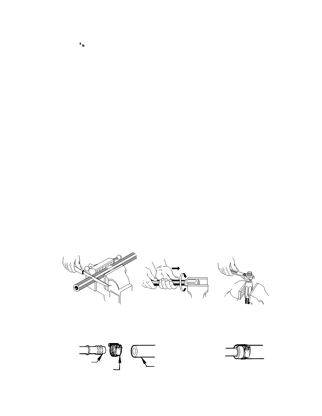
REFRIGERANT HOSE INSTALLATION
MAKE CERTAIN O-RINGS ARE ON ALL REFRIGERATION FITTINGS BEFORE SECURING.
2.
Screw hose into collar
(left hand thread) until hose
bottoms. Back out 1/4 turn.
3.
Screw fittings into collar until
insert bottoms. (Lubricate insert
and I.D. of hose for ease of
assembly).
1.
Cut hose to proper length.
Figure 2 – REUSABLE FITTINGS (R-12 SYSTEMS ONLY)
3.
Attach Hose clamp to hose
assembly with space bar over
cut end of hose as show
2.
Push hose onto fitting until
hose bottoms against stop
1.
Cut hose as above in Fig. 2
Hose Clamp With Space Bar
Freon Hose, Fitting & Clamp Assembly
Push-On Freon Fitting
Freon Hose
Figure 3 – PUSH ON FITTING (R-12 SYSTEMS ONLY)