


 802 / 1003

RD-3-9098-0 (REV B)
PAGE 1
NOTE:
1.
Please read instructions all the way through, making sure you have all the parts and tools.
2.
While working on or around a vehicle, disconnect the battery to prevent accidental start-up or
electrical shorts.
3.
It has been established that R-12 refrigerant does deplete the earth’s protective ozone layer. Use
care so as not to release this material into the atmosphere.
4.
A/C systems operate under high pressure. At 77°F the R-134a container will be pressurized
to approximately 80 psi. Use caution when working with these materials. Goggles are
recommended.
5.
To function properly the A/C system must be clean and dry. Keep caps or protective covers
on all hoses and fittings until final assembly.
BEFORE STARTING
1.
A compressor, compressor bracket, belts and refrigerant hoses are required to complete the
installation. These items may be obtained from your RED DOT Distributor.
2.
The compressor must have sufficient capacity to allow the unit to deliver the rated BTU output. A 8
cubic inch compressor turning faster than 1,750 rpm is required.
3.
A fresh air filter, 78R 5000 is available for use in dusty environments. Replacement element for filter
is 78R 5200. For pressurizing the cab and drawing fresh air, 78R 5110 remote mount filter is also
available with booster blower (73R 9202 - 12V or 73R 9204 - 24V).
MOUNTING THE UNIT ON CAB ROOF
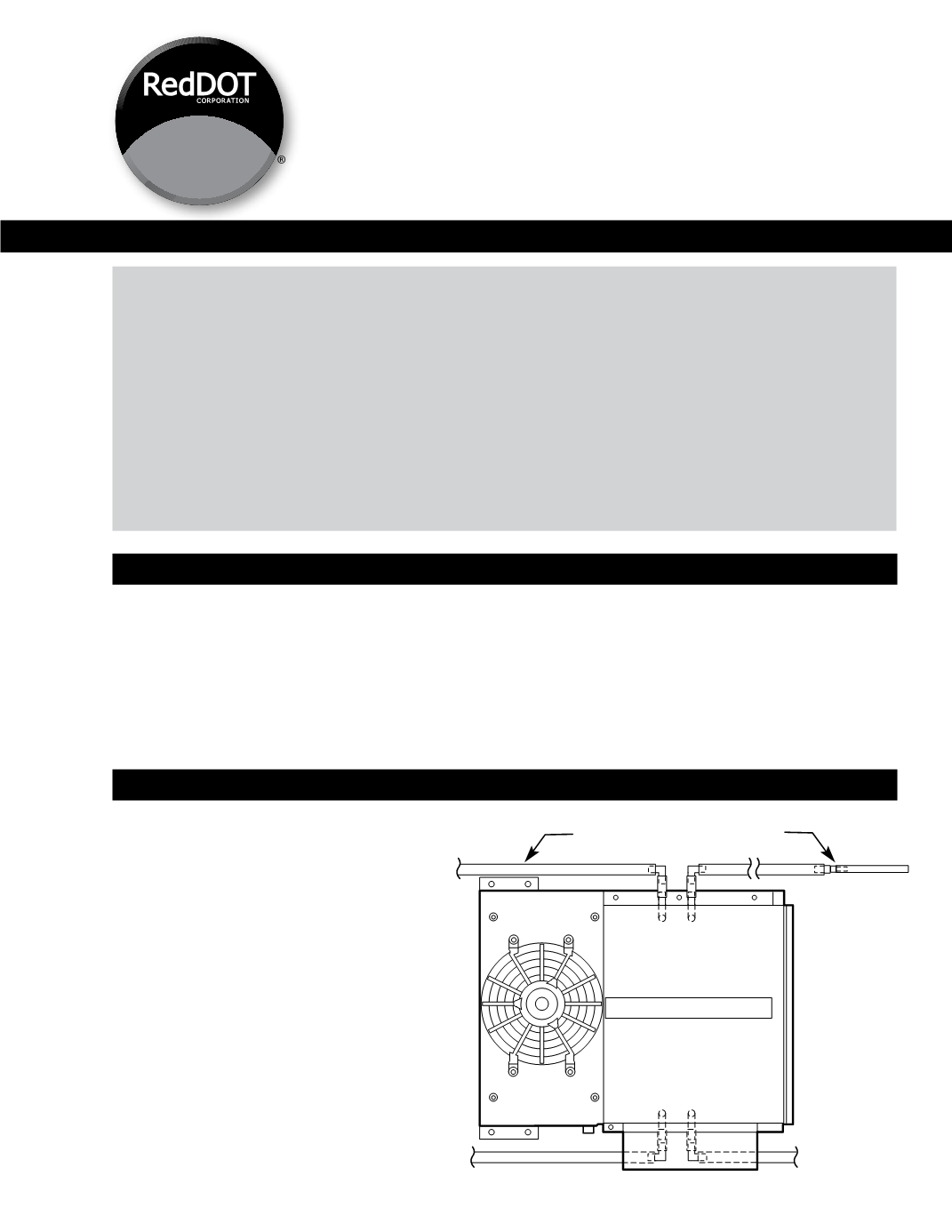
1.
Connect drain hose assembly as
provided in the installation kit (RD-3-
7142) to the unit.
(See Figure 1)
2.
Determine the location for mounting
the air conditioner unit per Red Dot
template.
a.
Refer to Figure 2.
b.
Mark the front-to-rear centerline
of the cab on the outside of the cab
roof.
c.
Place the mounting template
on the roof using the centerline as a
guide.
INSTALLATION INSTRUCTIONS
Rooftop
Heater/Air Conditioner
Model R-9757
Siphon Tube
Assembly (4)
Hose
DRAIN HOSE INSTALLATION
Figure 1