


 808-809 / 1003

RD-3-9821-0 (REV D)
PAGE 2
4.
Cut the rectangular inlet and outlet holes into the roof where marked (stay inside the lines). Then
remove the headliner and drill the
1
⁄
2
" (13mm) dia. mounting holes. Remove burrs and sharp edges.
NOTE:
The rectangular holes should go through the headliner, the mounting holes should not go
through the headliner. If the headliner is difficult to remove (or if the cab has no headliner), drill the
1
⁄
2
" (13mm) dia. mounting holes through the headliner and use cap plug washers and cap plugs
(supplied with kit) in conjunction with the M10 mounting bolts as shown in figure 2.
5.
Clean the outside roof area around the cut-out and mounting holes using a mild solvent.
6.
Apply a bead of sealant around upper surface of roof cut-out and mounting holes. Completely fill
bolt holes with silicone to ensure proper sealing.
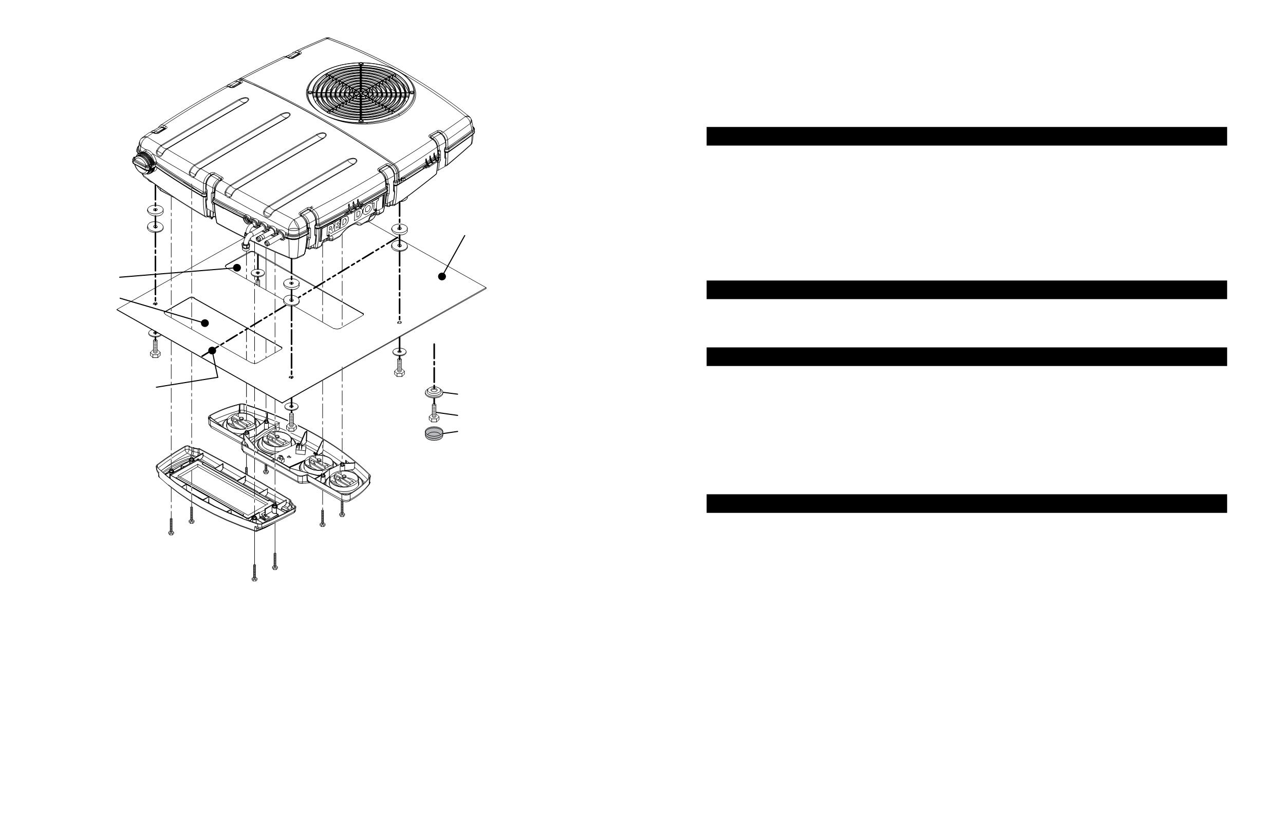
Also, place two rubber tapered spacers on each
of the mounting holes and rotate the spacers relative to one another to level the unit on the
roof
(figure 2).
WARNING: You must install the spacers to ensure adequate vibration isolation
of the unit.
R-9777 Unit
Recirc
Plenum
Vehicle Centerline
Discharge Air
Recirc Air Inlet
3 8
" Washer
MIO x 1.5 Bolts
(4 pieces)
M5 x .8 Bolts
(8 pieces)
Tapered
Rubber Spacers
REQUIRED
(8 pieces)
Inlet
Plenum
Cab Roof
Alternate Mount for
Exposed Bolts
with No Headliner
Caplugs
®
Washer
M10 x 1.5 Bolt
Black Caplug
®
FRONT
Figure 2
RD-3-9821-0 (REV D)
PAGE 3
7.
Set unit on cab.
8.
Apply sealant around bolts to prevent water leakage into cab.
9.
Install four mounting bolts.
NOTE:
Do not use an impact wrench to install the mount bolts.
Do not exceed 20 lb-ft (27 Nm) torque on the mount bolts.
NOTE:
Apply adhesive sealant to the mounting hole locations as needed.
REFRIGERANT HOSE INSTALLATION
1.
Cut hose to proper length. Make cut at right angles to centerline of hose. Blow cut hose with clean
dry air after cutting to insure no foreign particles are left in hose. Install the appropriate steel bead
lock fitting on the end of the hose and crimp fitting using crimper No. 79R 1510.A #12 suction
line is recommended in place of the #10 for increased cooling capacity. Use a step up fitting to
accomplish this.
2.
Route hoses over the top of cab and down the back wall to the compressor. On tilt cab vehicles,
route hose to the cab pivot and then to compressor.
3.
Use clamps to secure hoses and prevent hose movement. Hoses must not come in contact with
hot vehicle components, exhaust manifolds, etc., and they should not be subjected to mechanical
abrasions.
SECURE DRAIN HOSES
1.
Secure drain tube with tie wraps.Attach to refrigerant hoses only if they run downhill properly.
NOTE:
Be cautious not to overtighten tie wraps. Otherwise the drainage may be restricted.
2.
Inspect to make sure that drain tubes are not kinked, especially at back of cab.
WIRING
NOTE:
Unit is wired for negative ground.
1.
Disconnect battery.
2.
Orange and black wires (condenser fan circuit):
Connect the orange wire to the ignition switch
supplied power through a 30 amp circuit breaker (15 amp/24V) and the black wire to ground.
3.
Red wire and black wires (motor blower circuit):
Connect the red wire to ignition switch supplied
power through 30 amp circuit breaker (15 amp/24V) and the black wire to ground.
4.
Green Wire (compressor clutch circuit):
Connect to compressor clutch. Route the wire around the
hinge point before connecting to compressor clutch on tilt-cab installations.
5.
See Wiring Schematic (RD-3-9609) provided in installation kit.
AIR DIFFUSER AND RECIRC PLENUM
1.
Reinstall the headliner (if it was removed).
2.
Place cable control converter through control panel (“D” hole from inside of plenum) then tighten
the nut on the outside of the panel over the converter. Push the control knob provided in the kit over
the shaft of the converter. (connect unit wiring to the rocker switch and the fan switch, refer to the
Wiring Schematic for terminal information).
3.
Place the control/distribution plenum assembly up to headliner so that it covers the large
rectangular cutout (curved side of the plenum toward the condenser end of the unit) and start one
of the mount bolts.
4.
Start the remaining bolts and tighten plenum assembly bolts evenly until the plenum fits snugly
against the headliner.
NOTE:
Do not use an impact wrench to install these bolts. Do not exceed 30 lb-in (3.4 Nm) torque for
plenum bolts.
5.
Remove the filter from the recirc/filter plenum by turning the quarter turn fastener counterclockwise
and then removing the grill and filter.