


 806-807 / 1003

RD-3-9821-0 (REV D)
PAGE 1
INSTALLATION INSTRUCTIONS
R-9777
Air Conditioner/Heater
NOTE
1.
Please read instructions all the way through, making sure you have all the parts and tools.
2.
While working on or around a vehicle, disconnect the battery to prevent accidental start-up or
electrical shorts.
3.
Use care so as not to release any R-134a refrigerant into the atmosphere.
4.
A/C systems operate under high pressure.At 77˚F (25˚C) the R-134a container will be pressurized
to approximately 80 psi (552 KPa). Use caution when working with these materials. Goggles are
recommended.
5.
To function properly the A/C system must be clean and dry. Keep caps or protective covers on all
refrigerant hoses and fittings until final assembly.
BEFORE STARTING
1.
A compressor, compressor bracket, belts and refrigerant hoses are required to complete the
installation.These items may be obtained from your RED DOT Distributor.
2.
The compressor must have sufficient capacity to allow the unit to deliver the rated BTU output.
An 8 cubic inch (131 cc) compressor turning faster than 1,750 rpm is required.
3.
For pressurizing the cab and drawing fresh air, 78R 5110 remote mount filter is available with booster
blower (73R 9202-12V or 73R 9204-24V).
MOUNTING THE UNIT ON CAB ROOF
1.
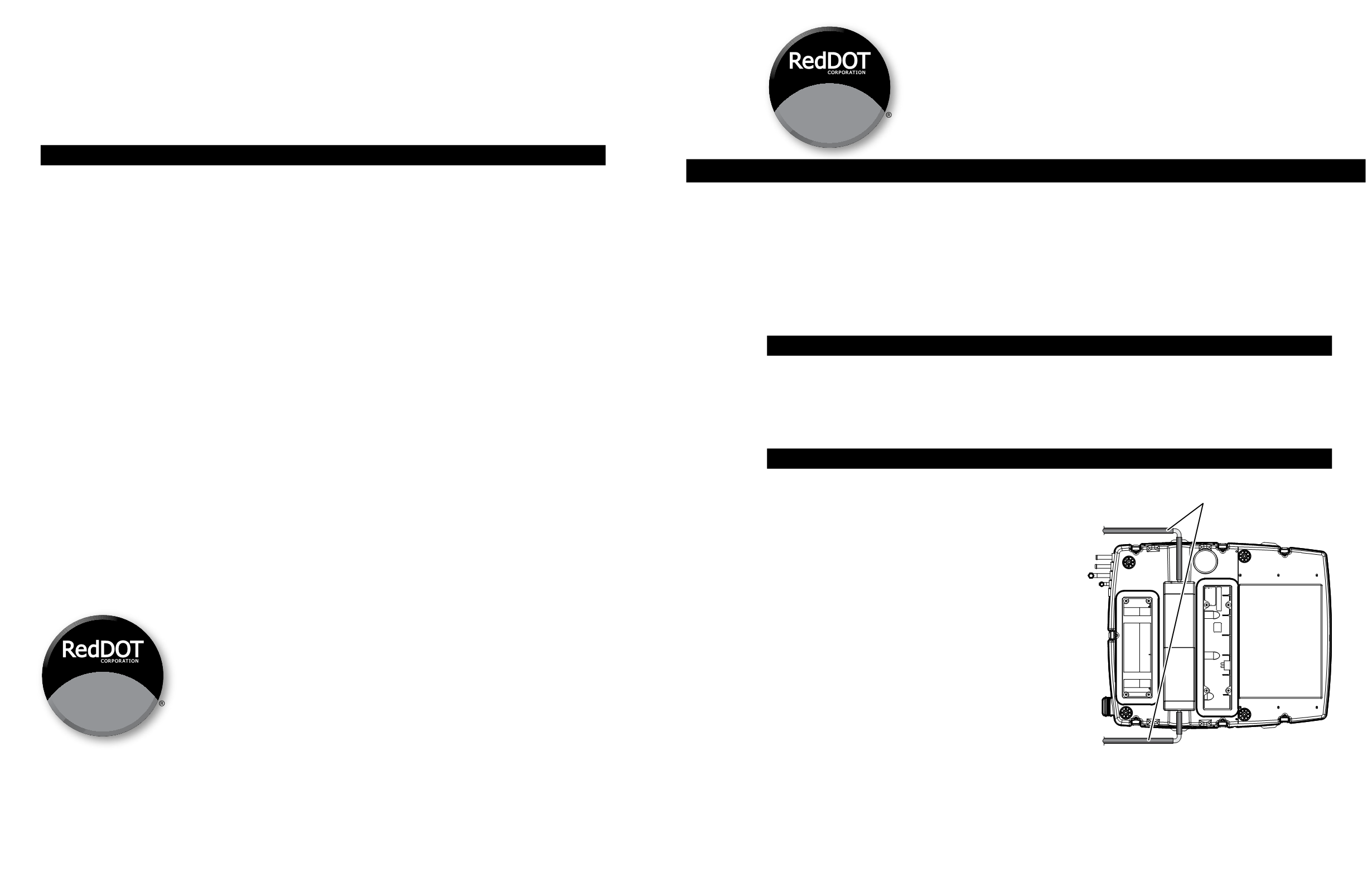
Connect drain hose and 90˚ elbows as provided in
the installation kit (RD-3-9146) to the unit.
(See Figure 1)
2.
Determine the location for mounting the heater-air
conditioner unit per Red Dot template.
a.
Refer to figure 2.
b.
Mark the front-to-rear centerline of the cab on the
outside of the cab roof.
c.
Place the mounting template on the roof using
the centerline as a guide.
d.
Ensure that air flow to the unit is not obstructed.
e.
Do not mount the unit with the front lower than
the rear, as this will prohibit water drainage.
f.
Avoid cutting roof stiffeners if possible. If stiffeners
are cut or roof is weakened due to the cut-out,
reinforcement may be required.
3.
Tape the template to the roof at the desired location.
Mark the roof cut-out area (scribe the roof).
NOTE:
Before taping the template to the roof,
decide what direction the unit is to be oriented. It is
recommended that the “recirc inlet” be to the rear
and the “discharge air” be positioned toward the front
of the cab (This puts the condenser at the front and
the plumbing to the rear).Also make sure that there is
clearance inside the cab for the plenums ‑ they are wider than the cutouts.
Drain Tube Assemblies
(hoses & 90˚ elbows)
Bottom View
Figure 1
RD-3-9821-0 (REV D)
PAGE 4
6.
Place the recirc/filter plenum up to the headliner so that it covers the small rectangular cutout
(curved side either away from or toward the condenser) and start one of the bolts.
7.
Start the remaining bolts and tighten the plenum assembly bolts evenly until the plenum fits snugly
against the headliner.
NOTE:
Do not use an impact wrench to install these bolts. Do not exceed 30 lb-in (3.4 Nm) torque for
plenum bolts.
8.
Replace the recirc filter and grill into the recirc/filter plenum.
FINAL ASSEMBLY AND CHECK
1.
Evacuate the system, test for leaks and charge with R-134a.The unit requires 1.8 to 2.2 pounds
(0.8 Kg to 1.0 Kg) depending on hose lengths.
2.
Connect the battery.
3.
Turn the ignition switch to the “on” position, turn the blower switch to the high speed position, flip the
a/c rocker switch to the “on” position:
a.
The a/c clutch should click on and be engaged.
b.
The evaporator blower should be turning at high speed.
c.
The condenser blower should be turning.
4.
Turn the fan switch to medium and low positions and check that the evaporator blower slows down.
5.
Turn the fan switch to the “off” position and compressor clutch should disengage.
6.
Start engine and run at 1500-2000 rpm.Turn unit on “full cold”,“high fan”. Check gauges for normal
pressures for R-134a.
7.
Check thermostat to be sure clutch cycles on and off.
Aftermarket Office P.O.Box 88790 Seattle,WA 98138
(206) 575-3840 fax (206) 574-6659
DISTRIBUTED BY: