


 13 / 44

April 2017
•
MechChem Africa
¦
11
⎪
Power transmission, bearings, bushes and seals
⎪
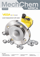
Varibox’s
ROTORcvt
is a two-stage
ratcheting CVT in
which the ratio adjustment
from a geared neutral is done via a 350 Watt
12 V electrical system. The prototype has been
implemented in a small passenger vehicle
and fuel consumption and mechanical
efficiency proved comparable to that of the
manual transmission version.
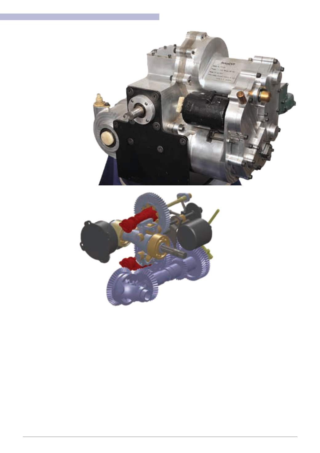
Left:
The ROTORcvt has rotor follower units
that operate rocker arms via their rollers. The
rocker arms take turns to drive the output gear
units using a ratcheting principle driven by the
strokes of the rotor follower units.
born in SA
Further describing the transmissionmech-
anismfor pulley-basedCVTs, Naude says that
the traction stresses at the friction interfaces
are another limiting factor of this technology.
“At themicroscopic level, the tractionfluid so-
lidifies at the steel-on-steel contact
point, keeping the band or chain
from directly contacting the pul-
ley. But because all of the traction
power has to pass through these
two friction points in series, the
contact pressures are very high.
The highest currently possible is
about 4.5 GPa, but this requires
high-strength steel and operates
at high temperatures. Reducing this
contact stress is another key driver
that underpins our alternative designs,”
he informs
MechChem Africa
.
Varibox solutions
Jan Naude has been developing
alterative CVT configurations since 2007.
“We focus on transmissions for vehicles and
for variable speed industrial applications.We
generally start with low power
options for small passenger
vehicles and thenwe strive
to scale them up. To date
we have developed three
different CVT products:
the icvt (incremental); the
ROTORcvt; and, most re-
cently, theRADIALcvt,” he says.
Describing the new radial CVT
configuration, he says that this system
uses three rollers with fixed diameters
as the input drivers and, because the
diameter is constant, “we can use a
constant clamping force to achieve the
necessary traction friction. This allows
us to use mechanical springs for clamping
instead of hydraulics, which removes com-
plexity, expense and weight.”
In addition, the input power is divided into
six parallel power paths – three rollers are
used to drive two disks in opposite directions
– on a common friction drive interface. “This
allows the metal-on-metal contact stress in
each friction drive to be kept below 2.0 GPa,
thus avoiding having touse expensivemateri-
als,” he notes.
“In addition, with our icvt and ROTORcvt
designs, although also unique, we have found
it difficult to get acceptance from the auto-
motive market because they use totally new
concepts andprinciples.With theRADIALcvt,
we have usedexisting parts, technologies and
principles in a new configuration, making it
easier for automotive OEMs to visualise and
analyse the practical
implications,” headds.
How does it work?
At its starting point the Varibox RADIALcvt
uses a shaft from the engine to drive a bevel
gear. This is connected to three splined radial
shafts that turn the three rollers that are120°
apart.
“The rollers are clamped between two
large driven disks, which rotate in opposite
directions. The output drive is recombined
by changing the direction of the one disk and
then coupling the transmission pathways
throughadifferential planetary systemto the
output shaft,” Naude explains.
Describing how the speed is varied, he
says: “The key principle is that the disks are
slightly conical (6.5°), the one being convex
and the other being concave. So by moving
the roller mounting structure in the direc-
tion of the input shaft, the radial drive rollers
are forced to move up or down their splined
shafts, changing the drive radius on the
driven disks.
The adjustment is achieved by rotating
the whole roller mounting structure on a
single lead screw. Thismoves thealignment of
the clamped discs through a range of around
12 mm relative to the position of the fixed
splines, which causes thepositionof the three
drive rollers to move closer or further away
fromthe axis of rotationof the clampeddisks.
“The screw mechanism is driven by a
100 W electric motor, which guides the
clamped structure along a set of three spiral
ramps around the casing.We use simple 12V
pulse width modulation-controlled (PWM)
motors similar to those used for windscreen
wiper speed control. This is very economi-
cal and very easy to interface with modern
CAN Bus vehicle control software systems,”
Naude notes.
The whole RADIALcvt system is very
narrow and it can comfortably be mounted
in front of the flywheel of any small car. The
prototype systemhas been designed for cars
below 50 kW. “Current automatic transmis-
sions for thesevehicles include the traditional
automatic fluid transmission, which is both