


 12 / 21

1
2
3
4
3Green+1Yello w
Bi
⋯
Bi
⋯
<
0.3M
0.7~0.9M
0.4~0.6M
0.3M
Bi
⋯⋯
Bi
⋯⋯
1
2
3
4
<
0.3M
0.3M
1.5M
0.4~0.6M
Bi………Bi………
1. Adjust the directions of sensors and axial orientation. Neaten the wires after installing the
sensors.
2. Connect the Red wire of the Control box to ACC, black wire to Ground, white wire to Reversing
signal wire, yellow wire to braking signal wire. Connect the date wires between Control box and
display.
3. Launching the car, the display shows the environmental temperrature inside the car.
4. Put one sensor (mark: E, F, G, H) into the corresponding outlet in the control box, display shows
".". If there's no obstacle in front, it means the system is in test status. Someone stands within the
distance of 0.7m should be detected. Disconnect the sensor, and test other sensors like this one
by one. After that, connect all the 4 front sensors to corresponding outlets.
5. When the driver engages the rear, the rear sensors should work.
6. When the driver disengages the rear, the rear sensors turn off and the front sensors work for 30
seconds.
7. When the driver presses brake pedal, the front sensors should work for 30 seconds.
Please be noted the following information while install and adjust the sensors (include front and back
sensors)
a
. If the buzzer sounds "BiBi.." after some sensor connect to control box, please check if there are
obstacles in front or beside the car, the sensor was installed too tight, the sensors under vibration
affacting to big part-near the electric wires , for example.
b
. If the alarm is the indication sound of
some area like "Bi...Bi..." while there is no obvious obstacle in front or beside, it maybe that the
sensor detected the surface of earth, please check if the directions of the sensor and axial oreitation
is correct, the level axial wire should be upraised, or it detects the outshoots like lisence Plate and so
on.
c
. If it still has problems after all above checking, the sensor may be broken or sensors don't
match to control box. The whole system shuld be changed.
d
. The sensors of the system should be
corresponding to the outlet of control box, while connecting to sensors, please pay attention to the
mark. e. while the distance of obstacle less than 0.3m, display would shows "0.0" instead of "0.2, 0.1"
to warn the driver to stop the car immediately.
0.0
0.7~0.9
0.4~0.6
0.3
5
6
7
1.3~1.4M
1.1~1.2M
0.7~1.0M
Bi………Bi………
Bi………Bi………
Bi……Bi……
Bi…Bi…
0.0
0.3
1.5
0.4~0.6
1.3~1.4
1.1~1.2
0.7~1.0
Operating Current: 30 - 180mA
Detecting Distance: Front (0.3 - 0.9m), Rear (0.3 - 1.5m)
Ultrasonic Frequency: 40KHz
o
Working Temperature (Control box): - 30 ~+70 C
o
Working Temperature (Display): - 20 ~+70 C
o
Temperature Display Range: - 30 ~+70 C
Display Size: 141.2*57.6*25.2mm
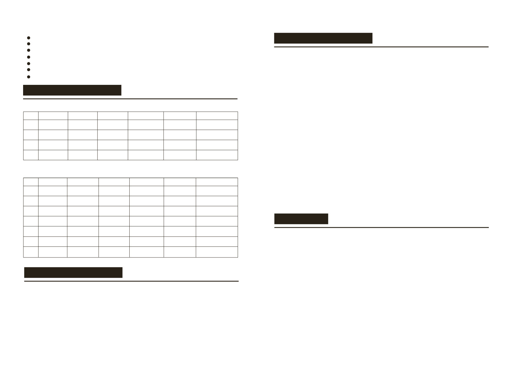
ALARM MODE
INSTALLATION STEPS
INSTALLATION AND TEST
NOTE
Stage 1
Stage 2
Stage 3
Stage 4
Stage Distance Four Stages Awareness
Alarm Color
Alarm Sound Digital Display
Danger Area
Alarm Area
Danger Area
Alarm Area
(Front detection)
(Rear detection)
1. The car must be in power-off when installing ultrasonic sensors
2. Its performance may be affected in following situation: heavy rain, gravel road, bumpy road sloping
road and bush, very cold, hot or moist weather, or the sensor is firned or iced over.
3. Switches among ultrasonic, electric wave, DC and AC and those among 24V, 12V voltages may also
effect its performance
4. The sensors should be installed appropriate loose or tight.
5. Its performance will be effected if the sensors are fixed on metallic bumper.
6. Avoid installing the digital control box in places of great interference, such as vent-pipe, wiring
nearby.
7. Test the system to make sure it works normally before using
8. This system is a reversing aid and the manufacturer will take no responsibility for any accident after
the kit is installed.
1. Choose right installation position for sensors
2. Select drilling position for sensor A & D(Select drilling position for sensor 1 & 4)
3. Select drilling position for sensor B & C(Select drilling position for sensor 2 & 3)
4. Locate the position and drill
5. Install the sensors and hide the wires
6. Install the display
7. Install the control box
8. Connect the whole system according to the General Installation Diagram
Stage Distance
Awareness
Alarm Color
Alarm Sound Digital Display
Four Stages
Stage 1
Stage 2
Stage 3
Stage 4
Stage 5
Stage 6
Stage 7
Alarm Area
Alarm Area
Danger Area
Danger Area
Bi………
Bi………
Bi………
Bi………
Safety area
Safety area
Safety area
3Green+2Yello w
3Green+2Yellow+1Red
3Green+2Yellow+2Red
1Green
2Green
3Green
3Green+1Yello w
3Green+2Yello w
3Green+2Yellow+1Red
3Green+2Yellow+2Red