


 9 / 21

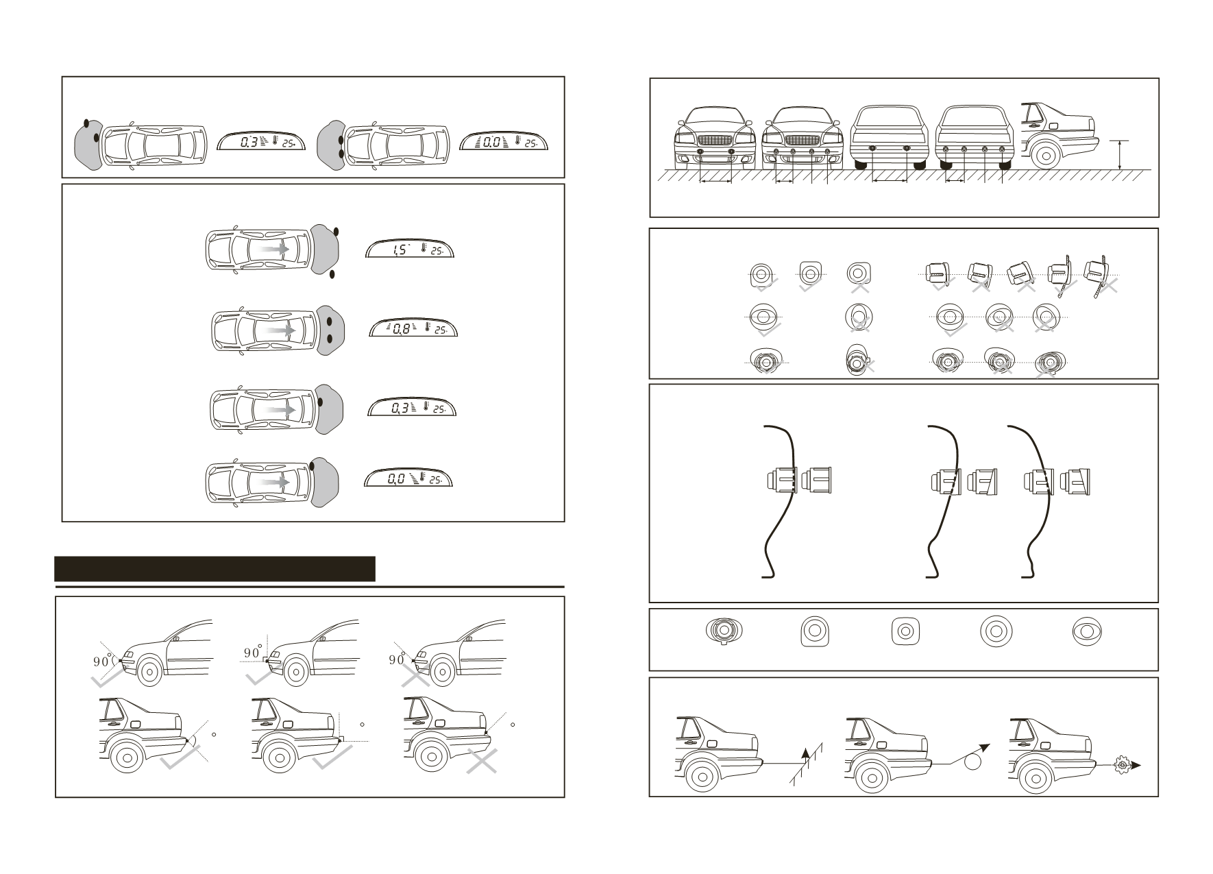
30cm
90
90
90
0.6-0.8m 0.3-0.4m
0.5-0.8m
0.6-0.8m 0.3-0.4m
30cm
110-150cm
40-100cm
<30cm
C
C
C
<30cm
C
C
C
Danger area
Danger area
Rear Detection
Safety area
Alarm area
Danger area
Danger area
SENSOR INSTALLATION DIAGRAM
Be sure no other part of vehicle falls into the detecting range of sensors to avoid false alarm.
Stick-on type
Insert-in type
The best position for 2 sensors The best position for 4 sensors
The direction of sensors (1)
Insert-in
Insert-in
Stick-on
The direction of sensors (2)
Vertical installation position to the ground Sloping installation position to the ground
Stick-on and insert-in sensors in various shapes for options
Objects hard to be detected
Smooth slope
Smooth round objects
Objects absorbing
wave, e.g. Cotton