


 21 / 36


August 2017
AFRICAN FUSION
19
Position
Layer Method Weld metal Wire Current (A) Voltage (V) Speed Gas flow (ℓ/min)
Long & circ welds on
backing plate & comp layer
1
GTAW
ERZr2
∅
2.4
120
∼
160
11
∼
13
8
∼
15 Main 8
∼
12; Side
30
∼
50; Back 3
∼
5
Long & circ welds on root
cover and composite passes
root
GTAW
ERZr2
∅
2.4
110
∼
150
11
∼
13
8
∼
15 Main 8
∼
12;
Side 30
∼
50; Back 3
∼
5
-
cover GTAW
ERZr2
∅
3.2 140
∼
180
11
∼
13
8
∼
15
Long weld on the zirconium
cylinder
1
PAW ERZr2
∅
1.2
150
∼
160
26
∼
28
20
∼
22 Ionic gas 8; Tail
30
∼
50; Back 25
∼
45;
Connecting pipe backing &
comp layer backing ring
root
GTAW
ERZr2
∅
2.4
110
∼
150 11
∼
13
8
∼
15 Main 8
∼
12;
Side 30
∼
50; Back 2
∼
3
-
cover GTAW
ERZr2
∅
3.2 140
∼
180
11
∼
13
8
∼
15
Steel & zirconium
1
GTAW
AG
∅
2.0
90
∼
120
11
∼
13
8
∼
15 Main 10
∼
15
Table 3. Welding parameters for zirconium composite layer, cover plate, connecting pipe and cylinder on the reactor.
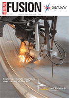
Figure 5. The welding and formation quality of the longitudinal welding seam.
The welding bevels for connecting
pipes on the cylinder are machined
using floor type boring and milling
machine. The root pass is finished by
manual GTAW with subsequent passes
being completed using SMAW. The pro-
cess is not complex. After welding of the
base layer, X-ray and ultrasonic inspec-
tion are performed on thewelding joint.
The entire weldment is then transferred
into the furnace for heat treatment.
The high temperature during heat
treatment reduces the peel strength of
the composite plate and the surface of
the composite layer gets over-oxidised.
With thedesignand related specification
being required, the holding temperature
should be low and the holding time
should be as short as possible.
Also, the inner shouldbe cleanedbe-
fore the heat treatment, and at least two
layers of titanium-based high tempera-
ture coating are necessary on the inner
wall. The heat treatment specification
for the reactor is 580 °C for three hours.
Welding of composite layer
The inner composite layer is commonly
made of ZR 700, R60700, while the back-
ingplateandcover plateare stillmadeof
R60702. ComparedwithR60702, R60700
has the similar welding ability and cor-
rosion resistance but the oxygen content
and the strength are slightly lower. It
can be directly explosion welded with
lowcarbon steel. The titanium is usually
added as the interlayer between R60702
and carbon steel to produce the zirconi-
um-steel composite plate [3]. Zirconium
is very active at high temperature and a
series of brittle intermetallic compounds
will form in the welded joint due to air
absorption, especially due to oxygen.
The welded joint will be embrittled.
The corrosion resistance and the
machiningproperty canalsobeaffected.
Therefore, in order to prevent gas pol-
lution during welding, it is necessary to
shield the weld joint using purging de-
vices. Pure argon (99.99%) is used in the
high temperature zone (≥400 °C) of the
weld joint and the weld seam is rapidly
cooled. The impure elements, especially
carbon, can greatly affect the corrosion
resistance of theweld seam. When there
is a small amount of carbon (>0.05%),
the corrosion resistance will be drasti-
cally reduced. Therefore, it is necessary
to clean the oil and other contaminants
on the surface of the welding part, to
prevent contamination [4].
The welding parameters for the
zirconium composite layer, cover plate,
connecting pipe and cylinder on the
reactor are shown in Table 3. The weld-
ing quality of the zirconium composite
layer is related to the long-termsafe op-
eration of the equipment. The welding
processes are introduced as per Table 3.
While welding between the back-
ing plate and composite layer, welding
gaps should be as even as possible
and must be between 1.0 and 2.0 mm.
If it is smaller than 1.0 mm, it cannot
guarantee the design requirements of
thewelding depth of 2.0mm. Otherwise
the base metal will melt and cause hot
cracking in theweld seam. If it is difficult
to control thewelding gap precisely, it is
better to let the welding gap be as small
as possible. Meanwhile, a 1.0 mm ×45°
groove is machined into the backing
plate so that the reinforcement of weld-
ing between the backing plate and the
composite layer is small. This can also
ensure welding penetration of 2.0 mm
according to the design requirements.
For thewelding between cover plate
and composite layer, there is always
misalignment in the longitudinal and
circumferential welding seam in the
cylinder. Hence the gap between the
welding seamof the cover plate and the
composite layer is different. When the
pair of cover plates is mounted, the gap
should be even and as small as possible.
Two welding passes are performed,
in which the arc ignition and arc blow
out locations are staggered. The first
welding pass is performed using aweld-
ing wire of
∅
2.4 mm. A small amount of
fillerwire, whichassures the full penetra-
tion of weld leg, is used.
The second welding pass is per-
formedusingaweldingwireof
∅
3.2mm.
The weld fill is normally finished when
the size of the weld leg is big enough.
Figure5 shows thewelder is operatingon
the cover plate and composite layer and
the forming quality of the weld.
It is worth noting that the high-
purity argon in the leak detection pipe
can replace the air at the back of weld-
ment to prevent contamination. While
Zirconium-steel cladding