


 6 / 12

Part No. PSP7410022
Page 6 of 12
The 3Ø PRS Programmer user interface is provided in the enclosed USB memory stick. Three (3) standard
USB type B mini male connector cables and one(1) USB hub (the cables with the hub set must be ordered
separately) are necessary to interface between the three 3Ø PRS units and the programmer.
PROGRAMMING
Insert the USB memory stick supplied into computer and follow the on-screen instructions to install the
3Ø PRS interface on the computer. A shortcut “Hubbell Three Phase Sectionalizer will be displayed on
the Desktop upon installation.
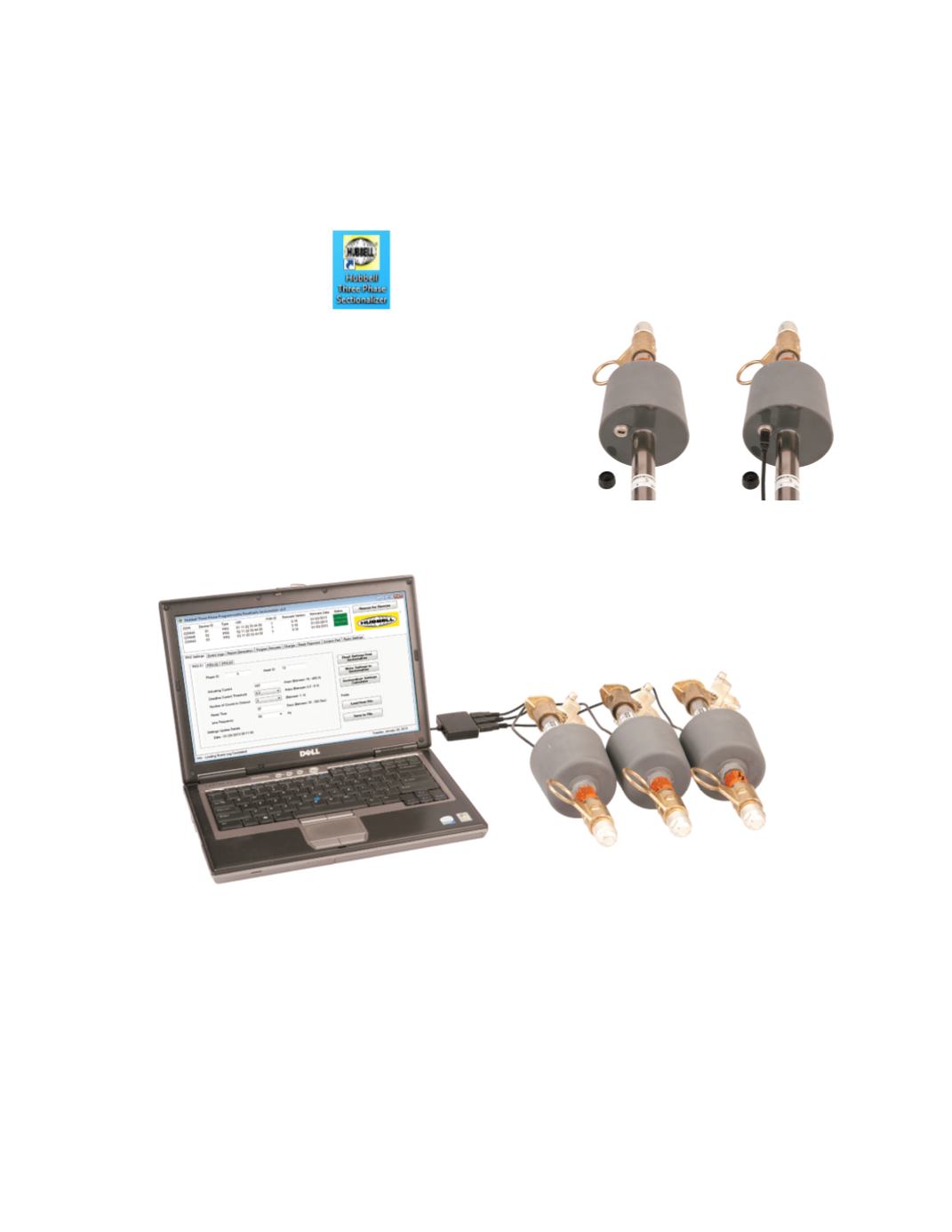
1. Unscrew the protective caps on the 3Ø PRS mini USB ports and
connect the three USB cable male sides to the Sectionalizer USB
port hub and the USB hub to the computer as shown in Figure 9.
2. Launch the Hubbell Three phase Sectionalizer programmer. The
software automatically searches for the connected devices. With
all the three 3Ø PRS connected and the same PAN ID pairing is
established for successful communication. If no devices are updated
click Rescan for Devices to make sure the PAN ID matches .Once the
communication is established the status of the units is highlighted
in green on the programmer.
3. User can change settings on the units only when all 3 units that share the same PAN ID are connected
but the user is allowed to Read Settings ,Generate Reports and Event Logs when connected to the
devices individually or altogether.
4. The main settings screen called the “ PRS Settings” (Figure 10) includes settings of all the 3 units
connected to the computer. Settings of the 3 units in one set are displayed in separate tabs. Settings
can be modified in "PRS-01" tab and upon clicking the "Write Settings to Sectionalizer" button, the
same settings will be written to the other 2 units in the set. The modified settings on the other two
units can be seen in the tabs "PRS-02" and "PRS-03" in a grayed out manner under their individual
settings tab. User can label Phase ID and Asset ID as needed. Phase ID can be one ASCII character
(letters, numbers or special characters)
Figure 9 Three 3Ø PRS units connected to the system through the 3 port USB hub
Figure 8