


 7 / 52

CONTROL SYSTEMS + AUTOMATION
• Avoiding excessive or cumbersome management plans
• Modular approach to functional design specification (URS)
• Recording the verification process
• Recording the validation process using the URS
Other subsidiary topics for discussion are:
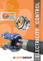
• Detecting and final control Elements
o The rise of programmable ormore accurately 'parameterable'
(if that’s a word) elements presents its own set of challenges
o Traditional detecting and final elements had a dedicated
single function. It did exactly ‘what it said on the tin’
o These elements continue to develop with self-teach func-
tions, floating muting, profile for safe minimum speed, etc.
o One must take care that with all the available flexibility,
that the required safety function is being executed
• Areas of most frequent sub-standard design
Figure 2: Areas of most frequent sub-standard design.
These figures are not based on recorded statistics, but from observa-
tion of many projects. The high error rate for final control elements,
is mainly due to non-safe rated components in a safety loop without
sufficient diagnostics, redundancy or insufficient Mean Time To
dangerous Failure (MTTFd).
Modular User Requirement Specification
On a large or more complex project, where there aremultiple suppliers
of major sections of plant, in addition these suppliers may be fromdif-
ferent countries with varying statuary regulation. This places greater
emphasis the URS and the Safety Management Plan. Hypothetically,
we are considering a project which covers many hundreds of square
metres, several thousand I/O (regular control) and different complexes
of machinery. It is a production process using a variety of complex
machinery. We are discussing the delivery of the safety system for
this. A modular approach to requirement specification of safety
functions and then building these modules into safety loops, creates
a clear and unambiguous statement. In broad terms, typical safety
loops can be grouped into the following (the list is not definitive):
• E-Stop
o Zoning
o Class of stop function (break for free run)
• Access Control
o Physical restraint with interlock or guard locking
• Presence sensing
• Muting or Bypass
o Safe speed
o Hold to run / Jog
• Process interlock
o Hazard materials
Rather than specifying the detail function of each complete safety
loop, of which there may be several hundred in a large complex
project, one chooses the modules that make up the loop. Some of
the benefits to this type of development are:
• Avoids repetition of stating the same function in each safety loop
• Transparent to the hardware or software platform being used
• Diagrammatic format tends towards a clear, and unambiguous
definition
• A revision of a module does not require it to be exhaustively
revised in every loop. Change it once at the module definition
and it is referenced to wherever it is called
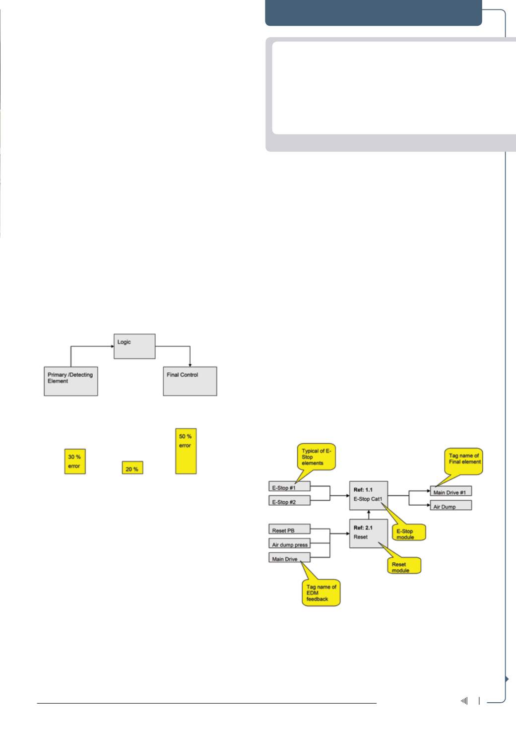
Figure 3: Example E-Stop loop.
In the example the module Ref 1.1 E-Stop and the module Ref: 2.1
Reset are specified for this particular safety loop. The Ref: 1.1 E-Stop
may be re used again and again in other E-Stop loops. All that changes
are the tag names of the input elements and output elements.
Abbreviations/Acronyms
CRC
– Cyclic Redundancy Check
EDM – External Device Monitoring
I/O
– Input/Output
IEC
– International Electrotechnical Commission
ISO – International Standards Organisation
MTTFd – Mean Time To dangerous Failure
PLC
– Programmable Logic Controller
PLr
– Performance Level
SIL
– Safety Integration Level
SRCS – Safety-Related Control Systems
URS
– User Requirement Specification
5
February ‘16
Electricity+Control