


 8 / 52

CONTROL SYSTEMS + AUTOMATION
Definition of a module
E-Stop Cat1 (Break Stop)
Refer to ISO 13850 E-Stop principles of design.
• E-Stop push buttons shall be dual channel (min Cat 3 architecture)
• There is no zoning of E-Stop functions. The E-Stop shall be global
to the defined area
• E-Stop contacts shall be normally closed of the self-monitoring
type, see hardware specification
• E-Stops shall adhere to the requirements of ISO-13850:2008
• The E-Stop category shall be Cat 1. i.e. break stop
It is recognised that the function of the E-Stop is to avert arising or
reduce existing hazards to persons, damage tomachinery or towork in
progress. It is not a substitute or alternative to any protective measure
such as a safety interlock to prevent access to mechanical movement.
Reset (Manual Monitored)
• All E-Stop functions shall be Monitored Manual Reset, requiring
External Device Monitoring (EDM) with the exception of safe rated
final elements with self-monitoring
• The reset shall be taken from the falling edge of the reset pulse
• The reset pulse shall be ‘AND’ with the EDM
• The reset command shall not be accessible fromwithin the hazard
area
Other examples might be presence sensing i.e. light curtains. The
behaviour of that particular module will define how it will respond
to inadvertent access – in other words a shut down to a safe condi-
tion. It will also define the behaviour under muting conditions, what
sequence it will have and time out, etc.
Recording of the verification process
The objective of the verification by analysis is to establish if the SRCS
shall function correctly and if it attains the required safety performance
level or SIL. IEC 62061 in particular calls for details about strategy, role
and identification of the people involved etc. There are different tech-
niques to adopt. The ‘top down’ approach such as Fault Tree Analysis,
or in the example below, the ‘bottom up’ approach. At a minimum
the following is required to record the process. There are a number
of core documents required.
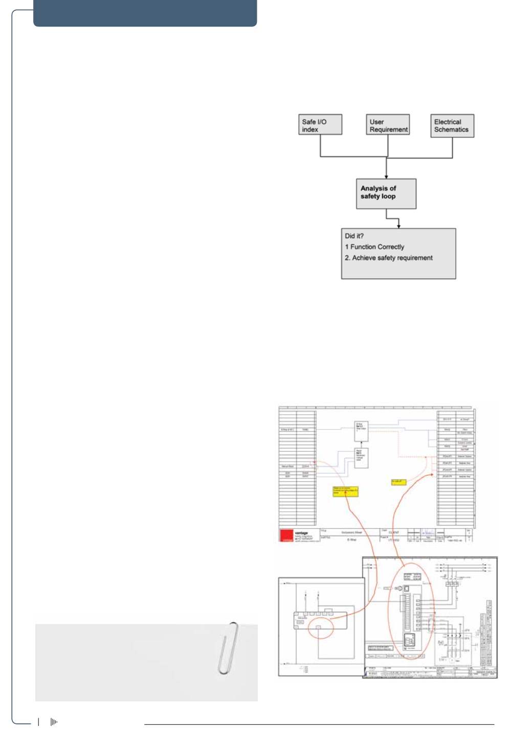
Figure 4
is a flow diagram showing how
the documents support the analysis to determine if the safety loop 1.
Functioned correctly and 2. Did it achieve the required safety level?
Figure 4: Flow diagram of analysis.
Example of analysis
• From the documentation the inputs and outputs for this E-Stop
safety loop are defined
• From the URS the function of the E-Stop and Reset are defined
• Error: From analysis it is found that there is no safe message
being passed to the final elements, and the Reset is Auto reset,
it should be manual
Figure 5: Example of analysis.
take note
• It is important to distinguish between a control system and a
‘safety-related’ control system.
• Whereastheformeroperatesallthetime,thesafety-relatedcontrol
system only has to respond when a demand is placed on it.
• Any design errors may only be detected too late – unless the
user requirement is properly specified.
Electricity+Control
February ‘16
6