


 1030 / 32

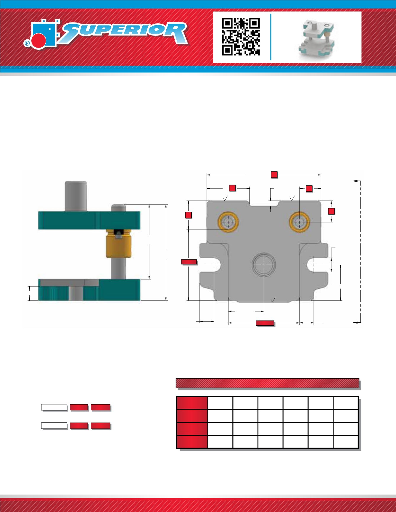
.375"
1.00"
TYPICAL
LENGTH/2
F*
(2)
DEPTH/2
1.00"
CENTRAL
1.00"
TYPICAL
LENGTH + (2)
A
A
**
1.00"
PIN LENGTH
PRESS FIT
PIN LENGTH
DEMOUNTABLE
PH
DS
VIEW A-A
CL*
CL*
CL
CL
LENGTH
DEPTH
All Superior Style 20 Die Sets are Two-Pin Back Post design with shape-cut work area with finished front and
back edges. They are offered in a wide range of sizes and come standard with a shank that is centered in
the work area. Left to Right feed (System LR) bushing clamp locations are standard.
Style 20 B -
The
Bolt Slot
Flange type die set offers a flame-cut bolt slot along with a machined clamping
surface on the edges of the die shoe. This classic design has long been the industry standard with proven
effectiveness.
WHEN ORDERING PLEASE SPECIFY:
1. Style 20 B, Friction or Ball Bearing
2. Quantity
3. Punch Holder (PH)
4. Die Shoe (DS)
5. Pin Type and Size
6. Bushing Type and Material
(1” or 2” Demountable Steel Shoulder Standard)
7. Shank Type and Size (if required)
8. For Ball Bearing Die Set Information
, See page 1110.STYLE 20 B DIE SET
Thickness
Depth Length
Thickness
Depth Length
* SEE BALL BEARING INFORMATION WHEN
ORDERING STYLE BB 20B
Note:
**
If
DS
≥
1¼”
,
thickness of flange is 1”.
1030
uncontrolled if printed or downloaded
If
DS
≤
¾”
,
thickness of flange
is DS thickness.
If
DS
>
¾”
<
1¼“
,
thickness of flange is ¾”.
STANDARD PIN LOCATIONS - FRICTION BEARING
3/4”
1”
1 1/4”
1 1/2”
1 3/4”
2”
PIN
DIAMETER
WORK
AREA (IN
²
)
F
1.750
2.000
2.250
2.500
2.750
3.000
CL
1.375
1.500
1.625
1.750
1.875
2.000
Upon
Application
Upon
Application
= < 36 = < 100 = < 225 = < 578
NOTE:
F Dimension refers to distance from edge of die set to inside
edge of pin. (Except on ball bearing die sets, See page 1110).