


 1070 / 32

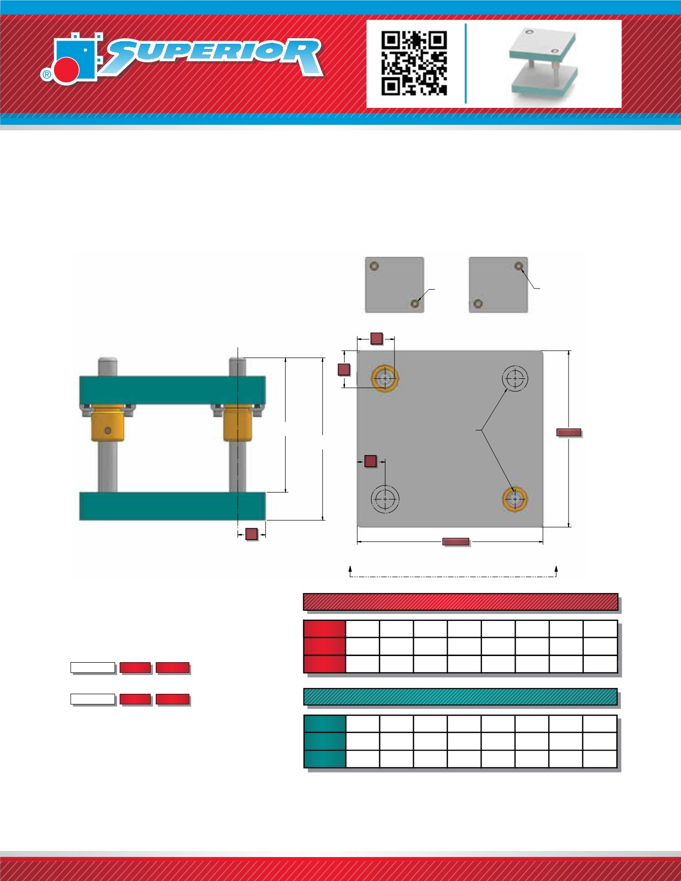
Superior Style 45 Two-Pin Rectangular Die Sets have guide pins located diagonally opposite at positions
“RR” or “LL” (see below). Style 45 Die Sets are furnished with guide pins of differing diameters to prevent
reversing of the plates during assembly. Left to Right feed (System LR) bushing clamp locations is standard.
Style 45 Die Sets are available in friction or ball bearing types.
STYLE 45 RECTANGULAR DIE SETS
WHEN ORDERING PLEASE SPECIFY:
1. Style 45, Friction or Ball Bearing
2. Quantity
3. Punch Holder (PH)
4. Die Shoe (DS)
5. Pin Type and Size
6. Pin Configuration (RR or LL)
7. Bushing Type and Material
(2” Steel Shoulder Standard)
8. Shank Type and Size (if required)
9. For Ball Bearing Die Set Information,
See page 1110.Thickness
Depth Length
Thickness
Depth Length
DEPTH
LENGTH
F
F
CL
A
A
CL
VIEW A-A
DIE SHOE
PUNCH HOLDER
STYLE 45
R-R
SMALL
DIA. PIN
STYLE 45
L-L
SMALL
DIA. PIN
PIN LENGTH
PRESS FIT
PIN LENGTH
DEMOUNTABLE
SMALLER PIN
NOTE:
Optional shank is located in center of work area.
All punch holder and die shoes stamped
MC “Matched Corner” regardless of pin location.
1070
uncontrolled if printed or downloaded
NOTE:
F Dimension refers to distance from edge of die set to inside
edge of pin. (Except on ball bearing die sets, See page 1110.)
CL Dimension for the smaller pin is the same as the large pin.
STANDARD PIN LOCATIONS - FRICTION BEARING
3/4
1
1 1/4 1 1/2 1 3/4
2
2 1/2
3
PIN
DIAMETER
F
1 3/4
2
2 1/4 2 1/2 2 3/4
3
3 3/4 4 1/4
CL
1 3/8 1 1/2 1 5/8 1 3/4 1 7/8
2
2 1/2 2 3/4
STANDARD PIN LOCATIONS - FRICTION BEARING - METRIC
19
25
32
40
44
50
80
PIN
DIAMETER
F
43,50 50,50 61,00 73,00 77,00 86,00
119,00
CL
34,00 38,00 45,00 53,00 55,00 61,00
63
99,50
68,00 79,00