


 1080 / 32

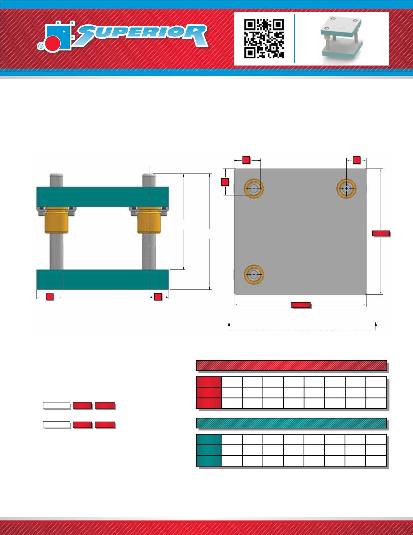
Superior Style 50 Three-Pin Rectangular Die Sets have guide pins located at any three corners. The three-pin
layout allows free movement of stock in the corner area wherever the pin is omitted. There is no offset pin
on Style 50 Die Sets. Left to Right feed (System LR) bushing clamp locations is standard. Style 50 Die Sets are
available in friction or ball bearing types.
STYLE 50 RECTANGULAR DIE SETS
WHEN ORDERING PLEASE SPECIFY:
1. Style 50, Friction or Ball Bearing
2. Quantity
3. Punch Holder (PH)
4. Die Shoe (DS)
5. Pin Type and Size
6. Bushing Type and Material
(2” Steel Shoulder Standard)
7. Shank Type and Size (if required)
8. Which Pin to Omit (ex. Omit Right Front)
9.
For Ball Bearing Die Set Information,
See page 1110Thickness
Depth Length
Thickness
Depth Length
NOTE:
Optional shank is located in center of work area.
uncontrolled if printed or downloaded
1080
NOTE:
F Dimension refers to distance from edge of die set to inside
edge of pin. (Except on ball bearing die sets, See page 1110.)
CL
DEPTH
LENGTH
F
F
A
A
F
CL
VIEW A-A
DIE SHOE
PUNCH HOLDER
CL
PIN LENGTH
PRESS FIT
PIN LENGTH
DEMOUNTABLE
STANDARD PIN LOCATIONS - FRICTION BEARING
3/4
1
1 1/4 1 1/2 1 3/4
2
2 1/2
3
PIN
DIAMETER
F
1 3/4
2
2 1/4 2 1/2 2 3/4
3
3 3/4 4 1/4
CL
1 3/8 1 1/2 1 5/8 1 3/4 1 7/8
2
2 1/2 2 3/4
STANDARD PIN LOCATIONS - FRICTION BEARING - METRIC
19
25
32
40
44
50
80
PIN
DIAMETER
F
43,50 50,50 61,00 73,00 77,00 86,00
119,00
CL
34,00 38,00 45,00 53,00 55,00 61,00
63
99,50
68,00 79,00
NOTE:
Optional shank is located in center of work area.
All punch holder and die shoes stamped
MC “Matched Corner” regardless of pin location.