


 1040 / 32

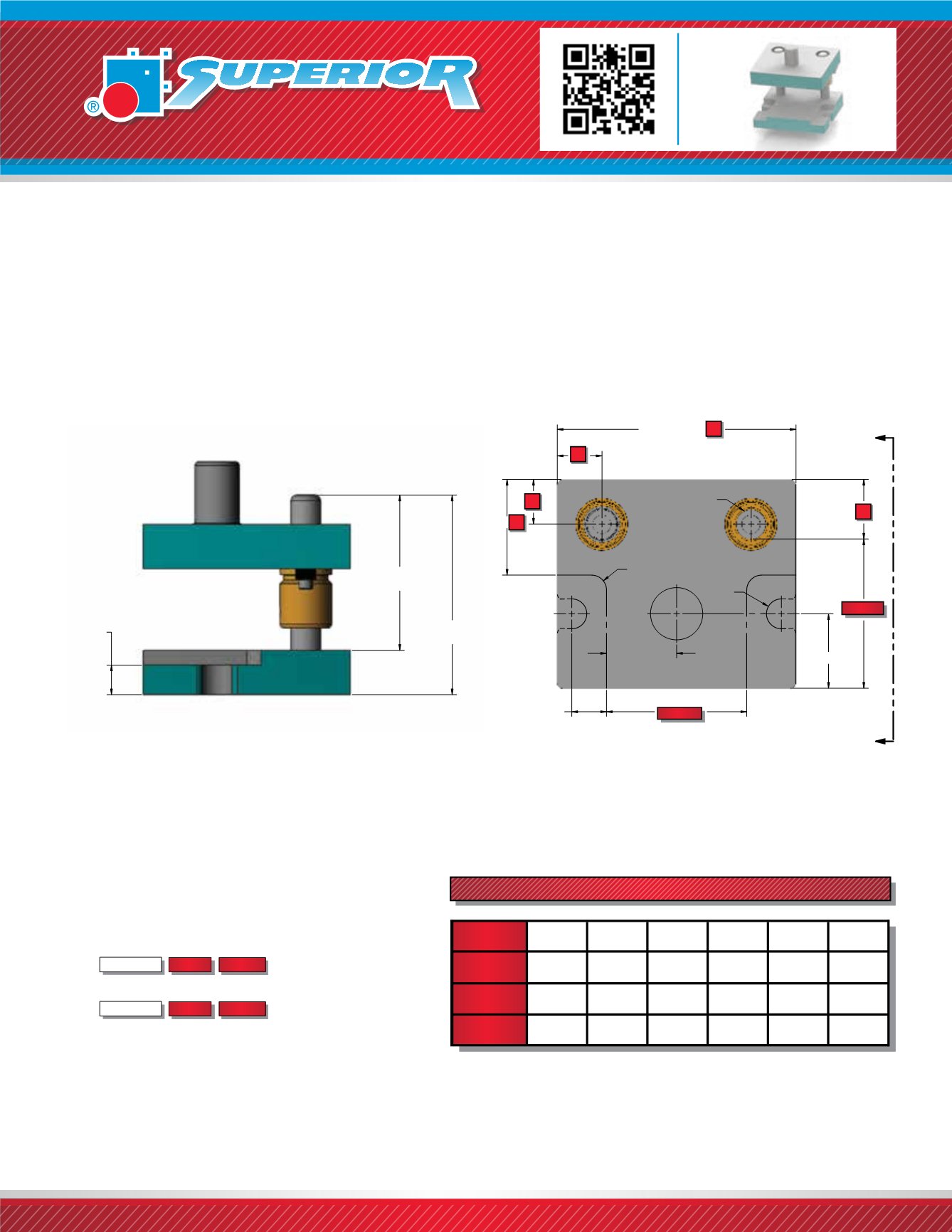
The Style 21 Die Set combines the features of our Style 20 Die Set but in a rectangular design. This helps to
maximize the work area in the punch holder yet still offers the clamping features in the die shoe. They are
offered in a wide range of sizes and come standard with a shank that is centered in the work area.
Left to Right feed (System LR) bushing clamp locations are standard.
Style 21 M -
Milled flange
has machined clamping surfaces only on the edges of the die shoe.
Style 21 B -
Bolt slot
has a bolt slot and machined clamping surfaces on the edges of the die shoe.
STYLE 21 DIE SETS
WHEN ORDERING PLEASE SPECIFY:
1. Style 21 M, 21 B, Friction or Ball Bearing
ex. Style 21 M, Style BB 21 B
2. Quantity
3. Punch Holder (PH)
4. Die Shoe (DS)
5. Pin Type and Size
6. Bushing Type and Material
(1” or 2” Demountable Steel Shoulder Standard)
7. Shank Type and Size (if required)
8. For Ball Bearing Die Set Information,
See page 1110.Thickness
Depth Length
Thickness
Depth Length
BELOW
SEE
NOTE
PIN LENGTH
PRESS FIT
PIN LENGTH
DEMOUNTABLE
PH
DS
VIEW A-A
LENGTH + (2)
.50R
DEPTH/2
.50R
1.00"
TYPICAL
(2)
LENGTH/2
A
A
PIN DIA.
DIE SHOE
CL*
CL
CL*
F*
LENGTH
DEPTH
CL
uncontrolled if printed or downloaded
1040
NOTE:
**
If
DS
≥
1¼”
,
thickness of flange is 1”.
If
DS
≤
¾”
,
thickness of flange
is DS thickness.
If
DS
>
¾”
<
1¼“
,
thickness of flange is ¾”.
PIN LENGTH
DEMOUNTABLE
PIN LENGTH
PRESS FIT
BELOW
SEE
NOTE
SHANK
OPTIONAL
VIEW A-
NOTE:
IF DS ≥ 1 1/4",
THICKNESS OF FLANGE IS 1"
IF 3/4" < DS < 1 1/4",
THICKNESS OF FLANGE IS 3/4"
IF DS ≤ 3/4", THICKNESS
OF FLANGE IS DS THICKNESS
.00"
T IC L
LENGTH
LENGTH + 2(CL)
CL*
CL
(2)CL
.50R
.50R
DEPTH/2
PIN DIA.
2.50
DEPTH
F*
A
A
PH
DIE SHOE
*SEE BALL BEARING INFORMATION
WHEN ORDERING STYLE BB 21
STANDARD PIN LOCATIONS - FRICTION BEARING
3/4”
1”
1 1/4”
1 1/2”
1 3/4”
2”
PIN
DIAMETER
WORK
AREA (IN
²
)
F
1.750
2.000
2.250
2.500
2.750
3.000
CL
1.375
1.500
1.625
1.750
1.875
2.000
Upon
Application
Upon
Application
= < 36 = < 100 = < 225 = < 578
NOTE:
F Dimension refers to distance from edge of die set to inside
edge of pin. (Except on ball bearing die sets, See page 1110).
*
SEE BALL BEARING INFORMATION WHEN
ORDERING STYLE BB 21B
NOTE:
All punch holder and die shoes stamped
MC “Matched Corner” regardless of pin location.