


 3 / 8
3 / 8

WHEN — Q3 2014
Dayton Parts LLC
(continued from page 2)
continued on page 4
3
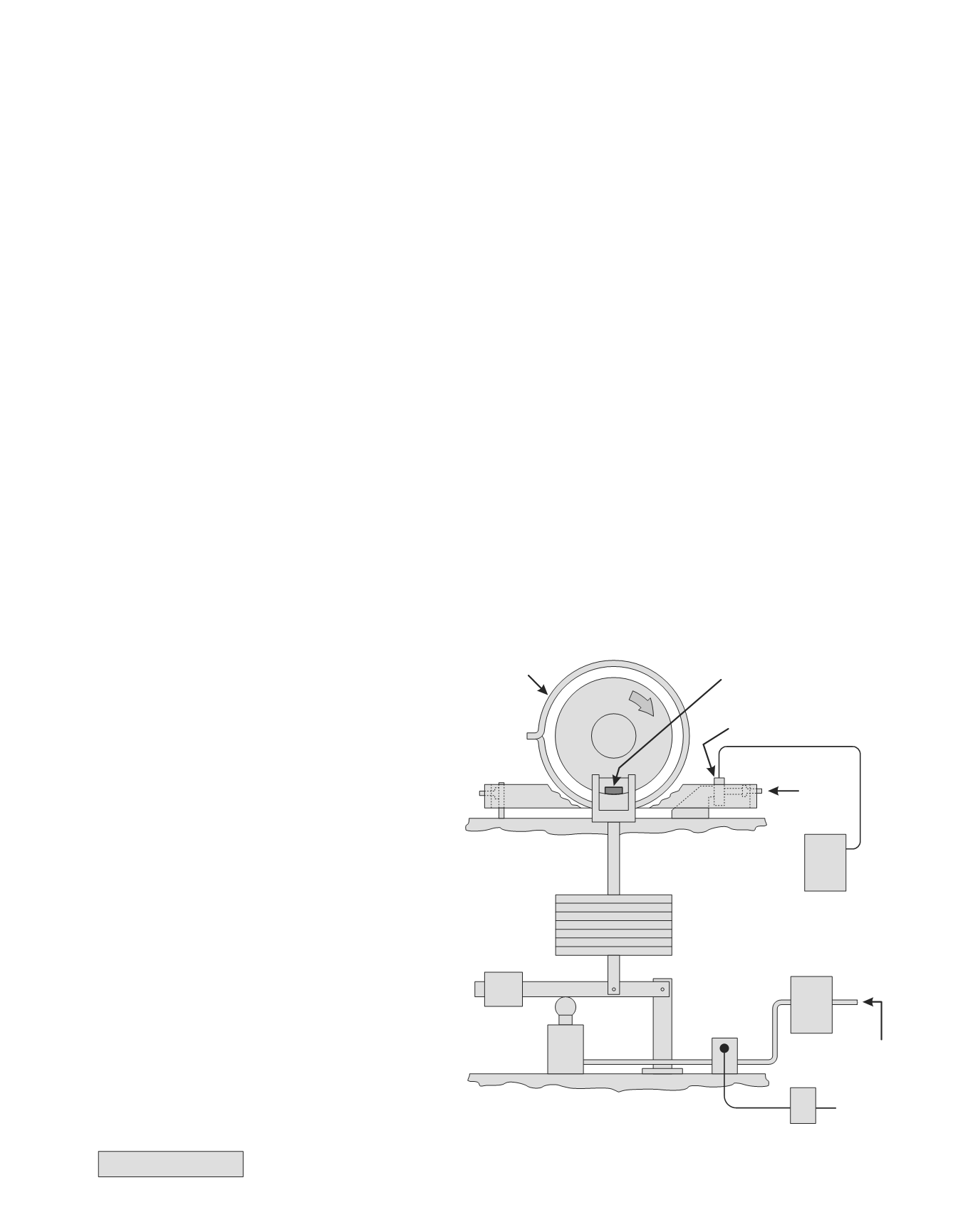
Friction Material Test Machine
Friction
Force
Load Cell
Test Sample
Auxiliary
Drum Heaters
Data
Recorder
Compressed
Air
Cycle
Timer
Electric
Power
Solenoid
Air Valve
Air
Actuator
Variable
Load
Pressure Regulator,
Filter, Gauge
From here on the history will be interwoven with the subject matter. The federal government and various air brake
system manufacturers along with the truck manufacturers begin to engage in a constant debate over standards,
rulings, regulations, etc. Nothing wrong with a healthy debate about something as important as safety but as we’ll see
in some cases, knowing you will always have the final word (like the federal government does) can lead to
overreaching. Next an important term used when talking about friction material that needs to be defined before
proceeding.
Coefficient of Friction
– One of the main values of friction material is the coefficient of friction (COF). The COF is the
ratio of force needed to overcome the friction between two surfaces. Here are a couple of examples to illustrate -
1. Let’s say you have a 100kg weight sitting on a level surface. In this case the amount of force keeping the
weight there is 100 kg (gravity). If it takes 100kg of force to move the weight then the COF is 1.0 (100/100 = 1.0).
Now let’s say you change the material the weight is sitting on and it only takes 50kg of force to move the weight.
The COF for the second material is .50 (50/100 = .50).
2. Now let’s say you have the 100kg weight back on the original material but this time you place another 100kg
weight on top of the first one. You now have 200kg (100kg x 2) of force keeping the weight there (like increasing
the air pressure during a brake application). Now try to move the 200kg of weight with the same 100kg of force.
What happens? Nothing, the weight won’t move. You’ll either have to increase the force you’re trying to move it
with or change the material and reduce the COF. The COF of the second material was .50 so let’s see what that
does. 200kg x .50 COF = 100kg and the weight will move.
I realize this is a very simplified illustration of what’s going on when you make a brake application but the math
doesn’t change (it just gets more complicated!). The COF can change with the selection of a different friction material.
Another main factor when testing brake performance is temperature as we discussed in the first edition of WHEN with
the article on value drums. Now back to the story at hand with the first friction material identification system.
FMSI Edge Code
– In 1964 the Friction Materials
Standards Institute (FMSI) got a two letter friction
material identification system approved based on a
Society of Automotive Engineers (SAE) test
outlined in 1958. This test uses a 1" square of the
friction material to measure the COF within a
specified temperature range. The first letter
indicates the cold stop COF which is the average of
four readings with the drum temperature between
200 and 400 degrees. The second letter indicates
the hot stop COF which is an average of 10
readings between 400 and 650 degrees taken over
the first fade/recovery and then the second
fade/recovery. Here’s a diagram of the original
friction material test machine –
The COF range for each letter code:
C — Not over 0.15
D — Over 0.15 but not over 0.25
E — Over 0.25 but not over 0.35
F — Over 0.35 but not over 0.45
G — Over 0.45 but not over 0.55
H — Over 0.55
SAE Test J661 with identification system
outline in J866 used by FMSI