


 18 / 84

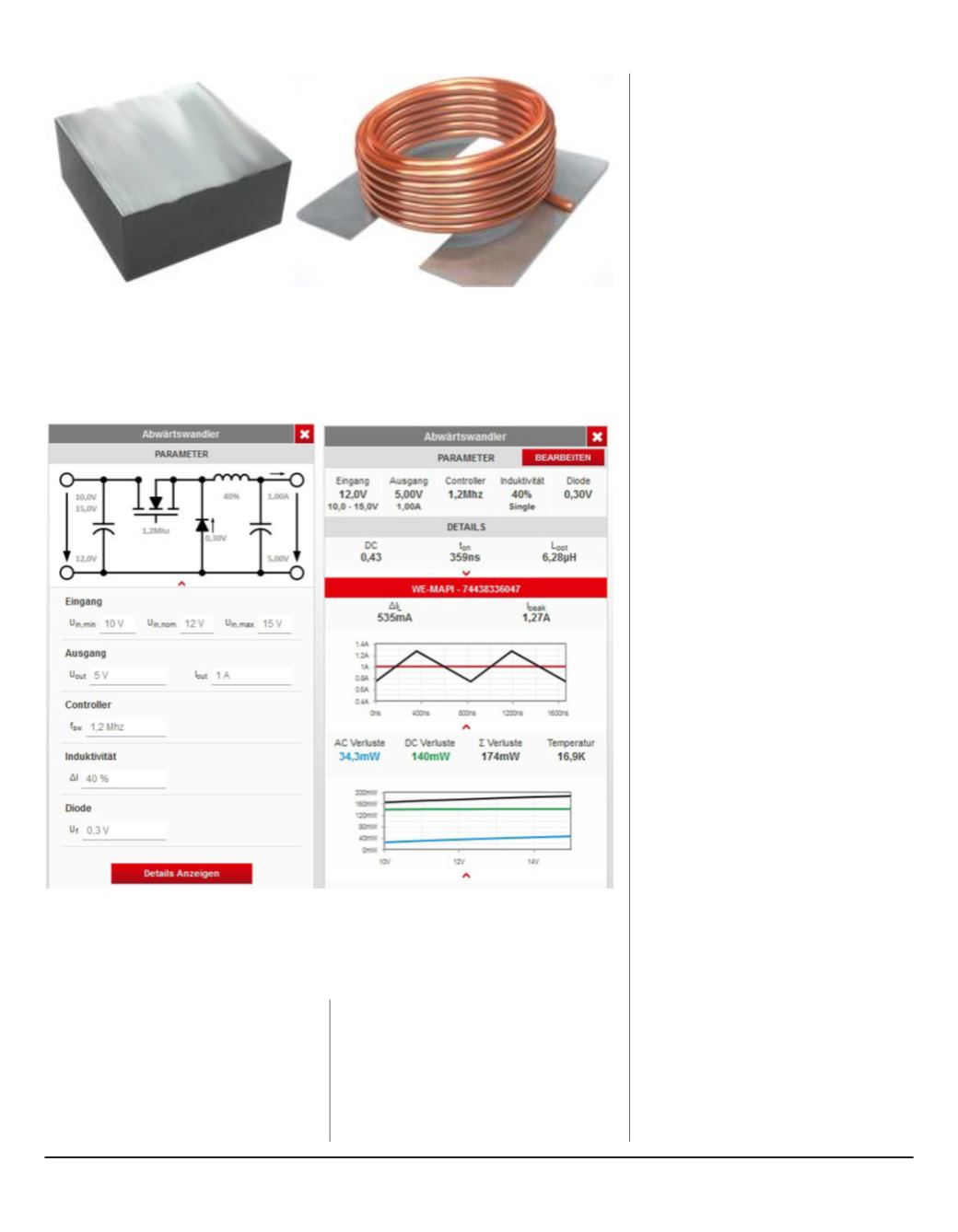
Figure 1: Outer package and core structure: core material losses
are reduced with the WE-MAPI coil
Figure 2: REDEXPERT User-Interface: the online tool calculates
ideal power inductance and estimates temperature
the core and soldered or welded to
the terminal with a clip. The outer
shielding ring is then mounted and
bonded with the inner core and the
winding. WE-MAPI is different: the
winding is contacted directly with
the component's connection pad
without soldering and welding. By no
longer requiring the clip, the effective
diameter was increased, thus
requiring fewer windings for the same
inductance values. This is directly
expressed in a considerably reduced
DC resistance (RDC) of the winding.
The core of WE-MAPI consists of an
innovative metal alloy pressed around
the winding. This gives the coil high
inductance values with a small package
size. At the same time, a self-shielding
effect is achieved by the special
construction of the core. The core
material itself is temperature stable
with little drift and soft saturation
behavior. A protective layer is also
applied around the core protecting
the surface against environmental
influences.
Losses in power inductors
The losses of power inductors are
driven by a combination of core
material losses and winding losses.
The latter can be divided into DC
current losses, principally influenced
by the DC resistance of the winding
(P=I2* RDC) and the AC losses (RAC)
of the winding that result from skin
and proximity effects.
In switching controllers, the coil is one
of the most important components
and therefore, accurate determination
of losses and heating is a key step in
the selection of the right component.
To predict heating, the AC losses must
be accurately determined first. Here,
the Dowell-, Ferreira- or Nan/Sullivan
methods are just some of the methods
used today.
Historically, core losses were
determined using the Steinmetz
model, and later with a modified or
generalizedSteinmetzmodel. Themain
drawback of the Steinmetz equation
is that it mainly applies for sinusoidal
excitations and determination of the
coefficients is usually only measured
with small signals. However, for most
applications in power electronics, the
coil current is not sinusoidal. And the
currents are large signals of several
milliamps (mA) up to several hundred
18 l New-Tech Magazine Europe