


 23 / 84

requires much effort to minimize
unwanted frequencies folding in-
band. This is the art of frequency
planning and involves a balance of
available components and practical
filter design. Some of the spur
folding concerns are briefly discussed
and the designer is referred to the
references for further explanation.
Figure 3 shows the folding of the
A/D input frequency and the first
two harmonics as a function of input
frequency relative to the Nyquist band
frequencies. For channel bandwidths
much less than the Nyquist bandwidth,
a goal for the receiver designer is to
select operating points that place the
folded harmonics out of the channel
bandwidth.
The receiver downconversion mixer
has additional complications. Any
mixer creates harmonics inside
the device. These harmonics all
mix together and create additional
frequencies. This effect is illustrated
in Figure 4.
Figure 3 and Figure 4 only plot spurs
up to the third order. In practice these
are spurs of additional higher order
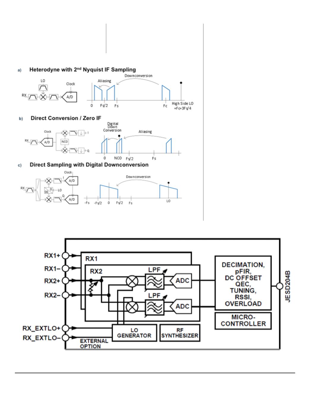
Figure 1: Frequency plan examples
Figure 2: Receiver section of the AD9371: A monolithic direct conversion receiver
to much improved image rejection.
The receiver section of the recently
released AD9371 is a direct conversion
receiver and shown in Figure 2; note
the similarity to Figure 1c.
Spurious
Any design with frequency translation
New-Tech Magazine Europe l 23