


 27 / 60


April 2016
MODERN MINING
25
COVER STORY
months in 2014 while Ivanplats awaited the
formal execution of its 30-year mining right.
Since then it has been all systems go with the
main focus of activity being the 7,25 m inter-
nal diameter, 975 m deep, concrete-lined No 1
shaft, one of the cornerstones of phase one.
When
Modern Mining
was on site recently, the
pre-sink had been completed to 54 m and the
shaft-sinking contractor, Aveng Mining Shafts &
Underground, was preparing for the slow sink
stage (the preliminary to the main sink) with
the 40 m high steel sinking headgear erected,
the five-deck stage in position in the shaft and
the final installation of the double-drum kibble
winder and four-drum stage winder underway.
According to Mouton, the shaft-sinking will
employ tried and tested traditional methods
using conventional jumbo drill rigs and cactus
grabs. “We would expect Aveng to achieve an
advance rate of 2,5 m a day once in full sink
mode and at this stage we are anticipating inter-
secting the Flatreef at a depth of 777 m in late
2017 with shaft bottom being reached in 2018,”
he says. “Although Shaft 1 is designated as the
primary ventilation intake shaft, we will be
hoisting through it as it will be used for early
underground development and this hoisting
role might become permanent as we move into
phase two.” He adds that development work
will include three stations at depths of 450 m,
750 m and 850 m below surface.
Shaft 1 is the smaller of the two main shafts
required for the full implementation of the
phase one Platreef project. The main pro-
duction shaft will be Shaft 2, which – once
completed – will rank as one of the biggest
shafts in the platinum mining field in South
Africa. Located just 100 m from Shaft 1, it will
have an internal diameter of 10 m and be sunk
to a depth of 1 250 m below surface. Capable of
hoisting 6 Mt/a, it will be equipped with two
high-speed 40-tonne skips running at 18 m/s
and will also be capable of conveying 225
persons in a single deck using a cage and coun-
ter-weight arrangement. At this stage, Ivanplats
is expecting to start early works for Shaft 2 in
2017, including civils work for the boxcut and
hitch foundation.
The headgear of Shaft 2 will be an impos-
ing concrete structure, 100,5 m high, making
it similar in size to the concrete headframe
of Impala’s No 16 shaft near Rustenburg. It
will accommodate two Koepe winding sys-
tems which will be positioned 82 m above
ground and – at a lower elevation – a single
drum auxiliary winder. The contract for the
design of the headframe – now complete – was
awarded to Murray & Roberts Cementation in
2014. Interestingly, the company has produced
a 1:260 scale model of the headgear using 3D
printing technology (see our photo), represent-
ing its first use of this technology. The model
was printed using ceramics as opposed to plas-
tics for aesthetic purposes, with the printing
process taking just 17 hours.
One of the reasons for the generous dimen-
sions of Shaft 2 is the fact that it will be used
to transport large trackless equipment under-
ground. Explains Mouton: “Based on the
recommendations of the PFS, we’ll be using
highly mechanised mining methods requiring
the use of some very large mining equipment
– for example, 40 and 50-tonne capacity min-
ing trucks and 14 and 17-tonne LHDs. These
machines will ‘live’ underground where we
will have workshops initially but, of course, we
have to get them down there in the first place
and also occasionally bring them to surface for
complete rebuilds. The dimensions of Shaft 2
will allow us to do this, although the bigger
machines will still have to be broken down to
allow them to fit within the cage.”
Transverse longhole stoping on a retreat
basis will the mining method applied to ore
zones with vertical thicknesses greater than or
equal to 18 m while thinner ore zones will be
mined using mechanised drift-and-fill or drift-
and-bench methods. Paste backfill will be used
for post-mining support although in the first
two years of production (prior to the startup of
the mill and the paste backfill plant) cemented
rock fill will be used as the fill system. Most of
the cemented paste fill (CPF) preparation sys-
tem will be located on surface with the only
underground components being the pipeline
distribution to the stopes.
Commenting on the use of longhole stop-
ing, Mouton says that the method – which is
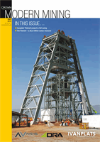
The stage and bank steel be-
ing lowered into Shaft 1.
“Although Shaft 1
is designated
as the primary
ventilation intake
shaft, we will be
hoisting through
it as it will be
used for early
underground
development and
this hoisting role
might become
permanent as we
move into
phase two.”