


 10 / 24

10
P817-1176
5—Installation
Preparation
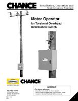
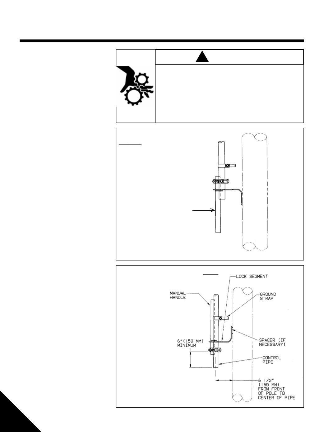
Step 1. — Modify Existing
Switch Handle
• Refer to Figures 3a and 3b
• Loosen and reposition ground strap clamp
so it is out of the way
• Establish how high the bottom of the enclo-
sure will be above the ground
• Cut off the control pipe a minimum of
34 inches (864 mm) higher than where the
enclosure’s bottom will be
• Remove the existing manual switch handle/
lock assembly (see Figure 3a) and re-
mount it upside down
(see Figure 3b)
NOTE: Drill the mounting hole for the lock
segment through the centerline of both
the control rod and the pole. This hole
must be perpendicular to both the
centerline of the control rod and the
pole to prevent binding between the
control pipe and the lock segment
when the motor operator is attached.
• Adjust the end of the control pipe so its
center axis is 6-
1
⁄
2
inches (165 mm) from
the face of the utility pole (see Figure 3b).
Use a spacer or adjustable lock segment
assembly if required.
External rods can move suddenly and unexpectedly.
This can pose a danger to the general public.
In areas accessible to the general public, this motor operator should
be installed with a minimum vertical height of 8 feet from the ground to
the bottom of the enclosure. If this minimum height cannot be
achieved, use shields, guards, enclosures or fencing to isolate the
motor operator from the general public.
Figure 3b – Switch Handle
After
Modification
Figure 3a – Switch Handle
Before
Modification
!
WARNING
Manual
Handle