


 12 / 24

12
P817-1176
5—Installation
Mounting
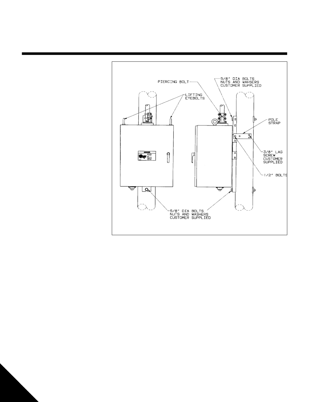
Step 1 — Mounting The Motor Operator
• Refer to Figure 5
• Ready lifting equipment to hoist motor op-
erator
NOTE: Lift motor operator by lifting eye-
bolts only.
• Attach lifting strap, chain or cable
safety hooks/shackles to lifting eyebolts
only. Strap, chain or cable and hooks must
be able to support 260 lbs (118 kg)
• Use spreader on lifting strap, chain or
cable so the motor operator is lifted
straight upward on the lifting eyebolts
• Hoist motor operator into position on utility
pole. Slip
5
⁄
8
inch bolt heads and washers
through the upper tear-drop shaped hole
and the lower slot in the mounting channel
• Lower motor operator until it is
supported by both bolts
• Torque nuts on mounting bolts to 25 - 28
ft
.
lbs (34 - 38 N
.
m)
• Assemble pole straps to each side of the
motor operator mounting channel where
shown in Figure 5 using
supplied
1
⁄
2
inch bolts, lock washers and
nuts
• Form the pole straps around the utility pole
(horizontally or diagonally) and tighten the
1
⁄
2
inch bolts
• Secure pole straps to the utility pole by
driving in
3
⁄
8
inch diameter lag screws (cus-
tomer supplied)
• Remove the lifting strap, chain or cable and
lifting eyebolts from the motor operator
• Place filler caps or
3
/
4
" bolt & rubber
washer (supplied) into
threaded eyebolt holes on enclosure
• Reattach/tighten lock segment and
control pipe to the utility pole
Figure 5 – Mounting Motor
Operator
Step 2. — Setting Overhead
Switch Position
• Close the overhead switch completely
• Include the switch manufacturer’s specified tor-
sional wrap-up
• Lock the manual switch handle in the closed po-
sition
• Reposition ground strap clamp, tighten and re-
connect ground wire
Step 3. — Attaching The
Switch Control Pipe
NOTE: Do not stand on motor operator enclo-
sure or use it as a step.
• Verify the motor operator and the overhead
switch open the same direction refer to Section
"Reversing Motor Rotation" if necessary.
• Verify the motor operator is in the closed position
before connecting to the closed overhead switch
refer to section "Energizing, Exercising and In-
specting" if necessary.
• Loosen drive casting U-bolts and in-
sert the switch control pipe in the drive
casting as shown in Figure 5. Tighten
U-bolt nuts until switch control pipe is
firmily held.
• Tighten drive casting piercing bolt
completely into the drive casting so
that it is completely seated, with no
threads showing
NOTE: Piercing bolt must be tightened
completely to assure alignment be-
tween switch control pipe and motor
operator.