


 11 / 24


P817-1176
11
5—Installation
Step 2. — Drill Mounting Holes
• Refer to Figure 4
• Mark upper hole location on the utility pole
by measuring 1 inch (25 mm) up from the
bottom of the control pipe.
Be sure this mark is on the control pipe
centerline (see front view, Figure 4).
• Mark the lower hole location on the utility
pole 34-
1
⁄
2
inches (875 mm) below the first
mark. This second mark must also be on
the same centerline as the switch control
pipe.
• Detach (unbolt) lock segment from the util-
ity pole and swing it out of the way to
make room for drilling the utility pole
NOTE: Binding will occur if the motor op-
erator mounting holes and the switch con-
trol pipe are not in alignment.
• Drill two
11
⁄
16
inch (18 mm) diameter holes
through the utility pole where marked as
shown in Figure 4
• Drill holes from switch control pipe side to
minimize alignment problems
• Assemble customer supplied
5
⁄
8
inch diam-
eter bolts, washers and nuts to the utility
pole
• Leave bolts sticking out of the control pipe
side of the utility pole to receive the motor
operator
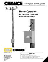
Figure 4 – Mounting Holes In Utility Pole
FRONT VIEW
SIDE VIEW
Drill 2 holes 11/16 inch (18mm)
diameter 34-1/2 inches (875 mm)
apart on control pipe centerline