


 9 / 24


P817-1176
9
4—Receiving & Handling
Components
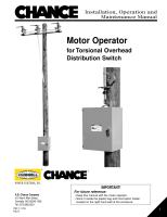
• Become familiar with the component
names and locations shown in Figure 2
• Open the motor operator door and identify
all the items shown in Figure 2
• Match the components in the following list
with those on the motor operator:
1. Lifting eyebolts
2. Rotation limit switches
3. Enclosure heater
4. Drive casting
5. Shift handle
6. Motor operator
identification nameplate
7. Control box
8. Manual motor rotation knob
9. Manual operating handle
10. Universal RTU receptacle
11. Ground lug and conduit fitting
12. Electrical terminal block 2
13. Radio Mount (if applicable)
14. RTU Panel (if applicable)
Figure 2 – Component Location
(1)
(2)
(3)
(4)
(5)
(6)
(7)
(8)
(9)
(10)
(11)
(12)
(13)
(14)
(1)