


 18 / 164

Immingham Storage Company Limited – East Terminal
No.7 Switchroom - Basis of Design
P & I Design Ltd
DOCUMENT NO: SI451001_RPT
2 Reed Street, Thornaby, UK, TS17 7AF
ISSUE: C DATE: 10.08.12
Tel: + 44 (0)1642 617444
PAGE 12 OF 12
Fax: + 44 (0)1642 616447
www.pidesign.co.uk7
LOAD SCHEDULE
The drive sizes quoted are from a site survey by Ian Stark and have not been further
verified at this time. A survey of the existing switchboards has however been conducted.
Several installed loads have been noted as redundant and have therefore been excluded
from the load schedule. It is to be confirmed by ISCo that this is correct. The redundant
loads are :-
1.
P3-18 (90kW)
2.
Phosphoric Acid trace heating T909/T910
3.
Full load currents are from generic tables and have not been confirmed from
motor rating plates
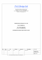
7.1
Loads Fed from 400A switch EE at No.3 Switchroom
Tag
Size
(kW)
Starting
Method
Full
Load
(A)
Duty
Drawing
Notes
P3-10
90 TBC
160
P3-11
18.5 TBC
35
P3-13
100 TBC
173
P3-16
45 TBC
83
P3-29
TBC TBC
TBC
P3-36
18.5 TBC
35
C3-31
75
100
Air Compressor (fed
from
100A
MCCB
therefore max running
current assumed to be
100A)
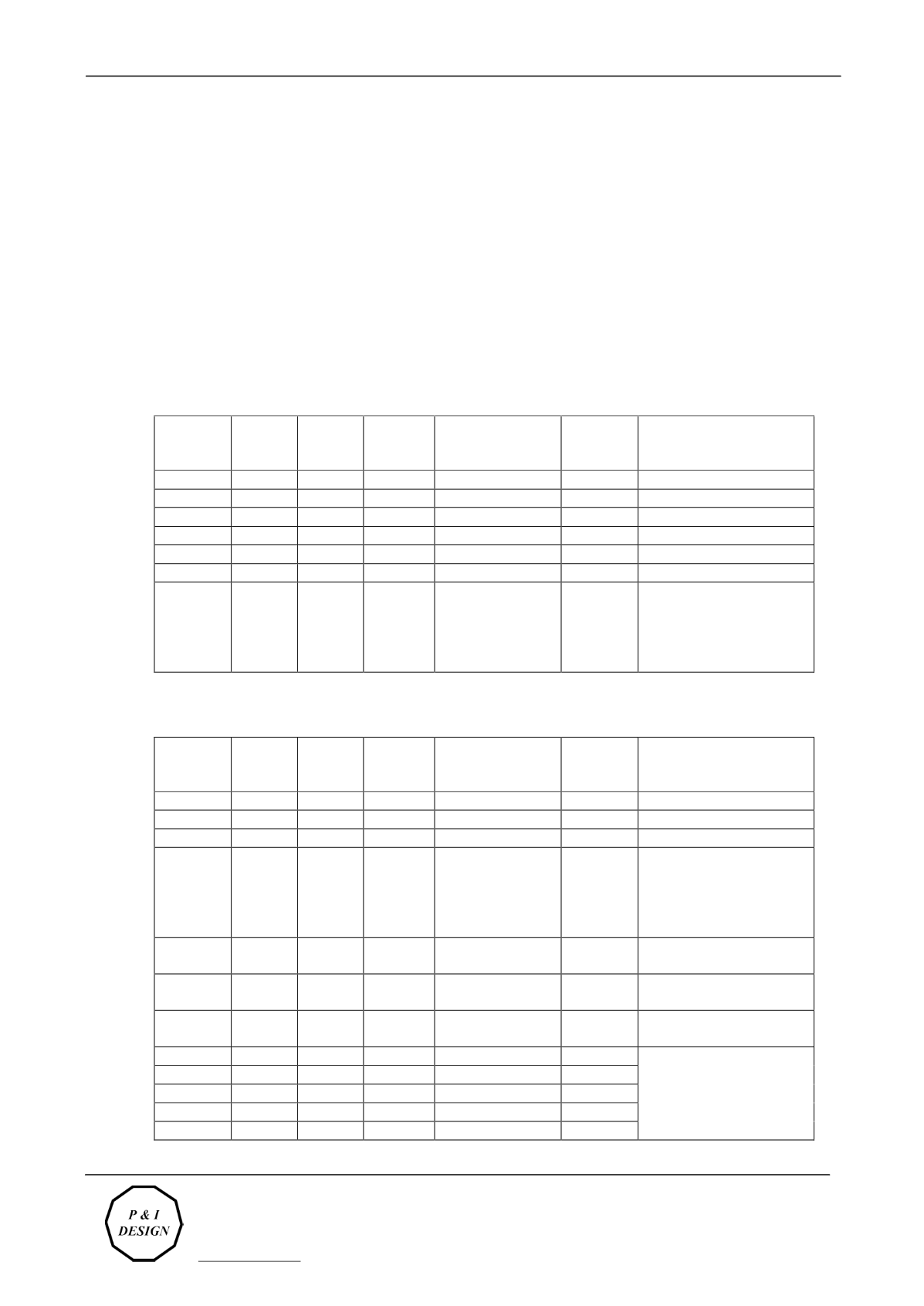
7.2
Loads Fed from 400A switch AC at No.3 Switchroom
Tag
Size
(kW)
Starting
Method
Full
Load
(A)
Duty
Drawing
Notes
P3-8
90 TBC
160
P3-9
90 TBC
160
P3-14
45 TBC
83
C3-32
75
100
Air Compressor (fed
from
100A
MCCB
therefore max running
current assumed to be
100A)
Jetty Derrick DB
200A MCCB – actual
load TBC
No.3 Pump
House DB1
No.3 Pump
House DB2
Site Lighting ?
P9-1
22 TBC
41
No.7 Switchroom Drives
fed from a 200A supply
in No.3 Pump House
P9-2
22 TBC
41
P9-3
22 TBC
41
P9-9
37 TBC
69
P9-11
37 TBC
69